Optimisation
The Optimisation group of the BlastMCF ribbon contains tools to run and manage BlastMCF optimisations.
Understanding BlastMCF
BlastMCF is a drill and blast design optimisation tool. It uses genetic algorithms to generate a number of drilling, charging, and timing design solutions within a predefined blast boundary.
BlastMCF generates these solutions against a number of targets. A target is a measurable outcome that the BlastMCF uses to quantify the quality of a design.
BlastMCF considers the following targets for a given design:
-
Cost — The total estimated cost of all components of the blast. This includes drilling, explosive product, primer, and estimates of labour costs involved. These are calculated through the same mechanism as the cost report in BlastLogic.
-
Fragmentation — An estimation of the distribution of rock sizes that will be produced by the blast. This uses the KuzRam model to estimate this distribution. See Fragmentation Modelling for more details.
-
Vibration — An estimation of the vibration caused by the blast at specified locations of interest measured as Peak Particle Velocity (PPV). See Vibration Modelling for more details.
-
Powder factor — The ratio of explosive mass per unit mass of rock to be blasted.
-
Fly rock projection — The predicted maximum horizontal distance that fly rock can travel as a result of blasting. Fly rock projection is based on either the McKenzie, C.K, 2009 or Richards and Moore, 2006 models. Note that the BlastMCF calculates 2D fly rock projection only.
Measuring targets
Targets can be either objectives that are optimised or constraints that are adhered to. If a target is set as an objective, the more optimal the design against the objective, the higher BlastMCF rates the design. If a target is set as a constraint, the target must fall within the user-specified minimum and maximum boundaries. If the BlastMCF cannot find a single solution that can satisfy the constraints, BlastMCF returns the result that is closest to meeting the constraints. However, this design solution is considered invalid.
To achieve optimum results, we recommend that you set competing targets. Competing targets are targets that optimise or constrain different aspects of a blast. For example, fragmentation and powder factor are non-competing targets because they are both related to oversize rock calculations.
The following table gives a description of how each target operates if applied as an objective or a constraint.
| Target | If Set As Objective | If Set As Constraint | Similar (non-competing) targets |
|---|---|---|---|
| Cost | BlastMCF will minimise the cost. | BlastMCF will discard any solution whose cost is outside the specified cost range. | |
| Fragmentation | BlastMCF will minimise the percentage of rocks that exceed the oversize rock diameter cutoff. | BlastMCF will discard any solution containing rock that is greater than the specified oversize rock diameter cutoff at a percentage greater than the fragmentation violation. For example, if an oversize cutoff of 1000mm was specified and the “percentile below cutoff” constraint was set to 90%, a fragmentation violation of greater than 10% would be discarded. This would represent less than 90% of the rocks being below 1000mm in diameter. | Powder Factor |
| Vibration | BlastMCF will minimise the average PPV of all monitoring points. | BlastMCF will discard any solution where the vibration results for any monitoring point exceeds that monitoring point’s limit. | Fly Rock |
| Powder Factor | BlastMCF finds the solution closest to the specified powder factor value. | BlastMCF will discard any solution with a powder factor outside of the specified minimum and maximum values. | Fragmentation |
| Fly Rock | BlastMCF finds the solution that produces the fly rock result that is furthest away from the specified exclusion zone boundaries. | BlastMCF will discard any solution that has fly rock that lands within the specified exclusion zone boundaries. | Vibration |
Note: You can set a target to be both an objective and a constraint. In this case, BlastMCF will optimise the solution between the set range and discard any solutions which are outside of the range.
Note: We recommend that you select a maximum of three competing objectives. Any more will result in very large processing times.
Run optimisation
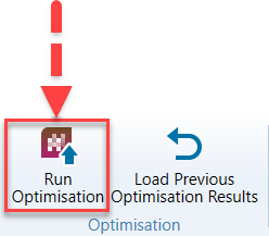
The Run Optimisation tool allows you to configure and run an optimisation. To do this, follow these steps:
-
Go to BlastMCF > Optimisation > Run Optimisation.
-
This will open the Run Optimisation panel with the following tabs:
- Optimiser settings
- Drill design
- Charge design
- Blast design
- Cost
- Fragmentation
- Vibration
- Powder Factor
- Fly rock

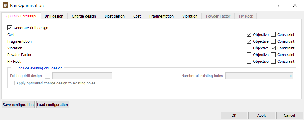
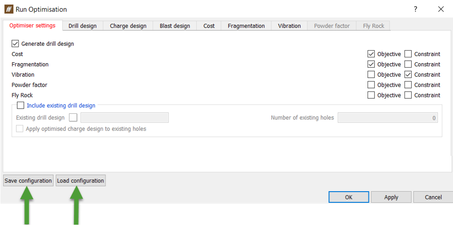
Configuring the Optimiser settings tab
The Optimiser settings tab include the targets you want to select and whether you want to generate a new drill design, use an existing drill design or both.
Configure the Optimiser settings tab by completing the following steps:
-
Choose from the following: Generate a drill design, Include a drill design, or both.
-
If you choose the Include a drill design option, you can further choose to apply the charge rule BlastMCF optimises on the included drill design. You can do this by checking the Apply optimised charge design to existing holes checkbox. If you leave the Apply optimised charge design to existing holes checkbox unchecked, the BlastMCF will use the current charge rule applied without any optimisation.
-
-
Choose the objectives/constraints you would like to include from the following options by checking the appropriate checkbox:
-
Cost
-
Fragmentation
-
Vibration
-
Powder Factor
-
Fly Rock
Including these targets will cause the corresponding tab to be enabled. If the constraint checkbox is checked, the associated options will also be enabled.
-
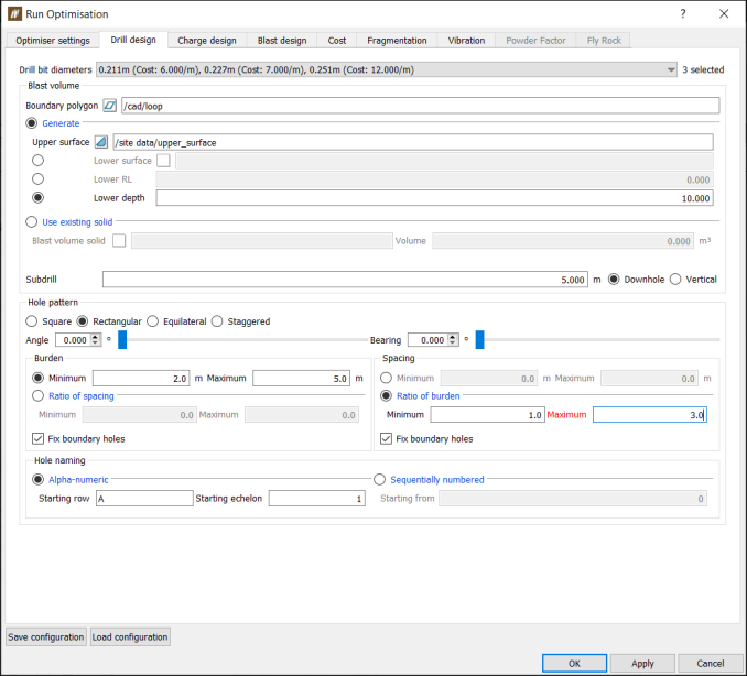
Configuring the Drill design tab
Configure the Drill design tab by completing the following steps:
-
Choose all of the applicable drill diameters you would like to consider in your drill design from the drill bit diameters drop-down list. BlastMCF will choose the optimal drill bit diameter from your selection.
-
Configure the following settings to generate a blast volume:
-
Set the Boundary polygon by dragging and dropping a polygon from the Project Explorer.
-
Choose to either:
-
Generate a blast volume by selecting the Generate radio button
-
Set Upper surface to a surface from the Data Explorer.
-
Set a lower surface by either one of the following options:
-
Supply a Lower surface from the Data Explorer by dragging and dropping the surface into the field.
-
Set the Lower RL where the lower surface will have the same Z value.
-
Set the Lower depth where all holes will have the same depth.
-
-
-
Generate a blast volume from an existing solid by selecting the Use existing solid radio button.
-
Set Blast volume solid to a solid from the Data Explorer by dragging and dropping the solid into the field.
-
-
-
Set the Subdrill field by entering a value. Choose from the following radio buttons: Downhole or Vertical. This will determine how the length of the subdrill is calculated.
-
-
Set the hole configuration pattern to one of the following options:
-
Square — The burden and the spacing are equal. Holes are placed in a square shape.
-
Rectangular — The burden and the spacing are not equal. Holes are placed in a rectangular shape.
-
Equilateral — The burden and the spacing are equal. Holes are placed in the shape of an equilateral triangle.
-
Staggered — The burden and spacing are not equal. Holes are placed in the shape of an isosceles triangle.
-
-
Set the Angle and the Bearing.
-
Set the Burden either by:
-
Setting the Minimum and Maximum burden.
-
Setting the ratio of spacing by entering Maximum and Minimum values. This means that BlastMCF will choose the optimal burden from a ratio of spacing between the minimum and maximum values provided.
-
Check or uncheck the Fix boundary holes. If you check this, BlastMCF will automatically adjust the burden of the holes that are around the boundary so that they are within the boundary.
-
-
Set the Spacing either by:
-
Setting the Minimum and Maximum spacing.
-
Setting the ratio of burden by entering Maximum and Minimum values. This means that BlastMCF will choose the optimal spacing from a ratio of burden between the minimum and maximum values provided.
-
Check or uncheck the Fix boundary holes. If you check this, BlastMCF will automatically adjust the spacing of the holes that are around the boundary so that they are within the boundary.
-
-
Configure the Hole pattern by completing the following settings:
-
Configure the Hole naming settings from the following options:
-
Alpha-numeric
-
Enter the Starting row.
-
Enter the Starting echelon.
-
-
Sequentially numbered. Enter a value for the Starting from field for the first hole.
-
Configuring the Charge design tab
BlastMCF allows you to optimise the how you charge your holes. There are three options you can choose from:
-
Optimise charge rule where BlastMCF optimises the parameters of an existing charge rule.
-
Apply charge rule where BlastMCF chooses the best charge rule from the provided options.
-
Optimise a simple charge plan with one explosive deck where BlastMCF optimises a plan designed on the fly. Use this option if you don’t want to use an existing charge rule.
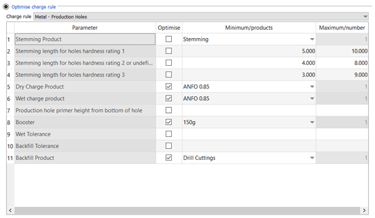
Option 1: Optimise charge rule
Choose this option if you would like to optimise the parameters of an existing charge rule.
Select a charge rule from the Charge rule drop-down list, which is populated from charge rules that have been loaded into the users cache. This will upload a list of charge rule parameters.
Choose to optimise any parameter from that charge rule by selecting Optimise.
For numeric parameters, if Optimise is selected, set the Minimum and Maximum value for numeric parameters.
For product parameters, if Optimise is selected, select the products you want to optimise from a drop-down list.
Option 2: Apply charge rule
Choose this option if you want BlastMCF to choose the optimum charge rule from a set of charge rules. From the Charge rules drop-down list, choose all the applicable charge rules.

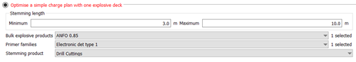
Option 3: Optimise a simple charge plan with one explosive deck
Choose this option if you want to quickly define a simple set of charge parameters without using a charge rule. These include:
-
Stemming length — Set a minimum and a maximum value and allow BlastMCF to find the optimal length.
-
Bulk explosive products — Select the applicable bulk explosive products from the drop-down list and let BlastMCF select the optimal product.
-
Primer families — Select the applicable primer families from the drop-down list and let BlastMCF select the optimal primer family.
-
Stemming product — Select the applicable stemming products from the drop-down list and let BlastMCF select the optimal stemming product.
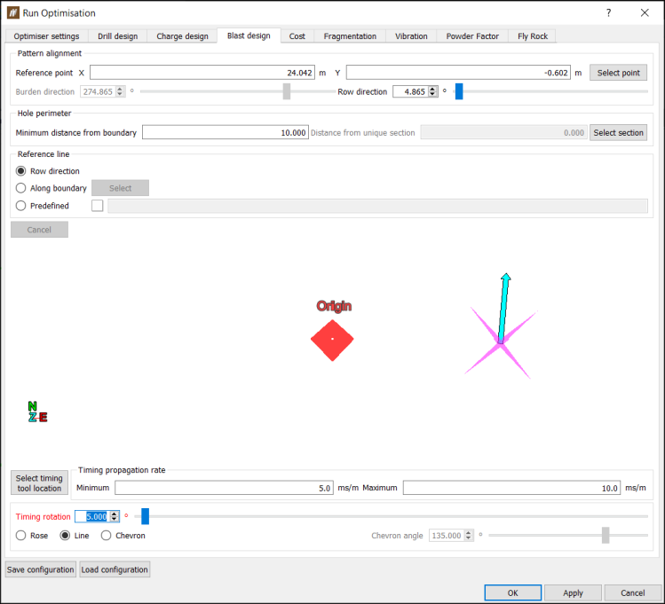
Configuring the Blast design tab
There are four separate sections to configuring Blast design:
-
Pattern alignment — Controls the start point of where the holes in the blast will be arranged, and in what direction.
-
Hole perimeter — Controls the blast perimeter.
-
Reference line — Controls where holes along a row are positioned.
-
Timing — Controls the blasting sequence of holes.
Configure the Blast design tab by completing the following steps:
-
Configure the Pattern alignment by:
-
Clicking Select point and selecting a point in the view in the panel. You can also manually set Reference point X and Reference point Y by entering values.
-
Setting the Row direction by entering a value or using the slider. This will automatically set the Burden direction which is a read-only field.
-
-
Configure the Hole perimeter by either:
-
Setting the minimum distance from the hole to the boundary by setting the Minimum distance to boundary field.
-
Setting the distance from unique selection by clicking Select section and then choosing a position in the view in the panel.
-
-
Configure the Reference line by either:
-
Setting a Row direction for the reference line.
-
Setting the reference line Along a boundary.
-
Dragging and dropping a line from the Project Explorer into the Predefined field.
-
-
Configure the timing tool by:
-
Clicking Select timing tool location and choosing a location in the view in the panel.
-
Setting the Timing rotation by dragging the slider.
-
Setting the timing tool to either a rose, a line, or a chevron. If the timing tool is a chevron, set a chevron angle by entering a value.
-
Setting the Minimum and Maximum timing propagation rate.
-
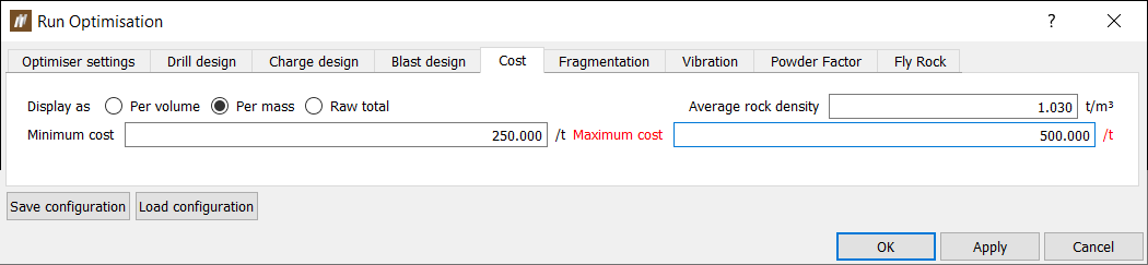
Configuring the Cost tab
Configure the Cost tab by completing the following steps:
-
Choose how to display the cost from the following options:
-
Per volume
-
Per mass. If this option is set, an Average rock density will be required.
-
Raw total
-
-
If Cost is a constraint, set the Minimum cost and Maximum cost.
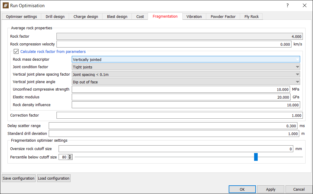
Configuring the Fragmentation tab
Configure the Fragmentation tab by completing the following settings:
-
Average rock properties
Either provide values for the rock factor and rock compression velocity or calculate the rock factor from the following properties:-
Rock mass descriptor
Choose from the following to describe the condition of the rock: Powdery/friable, Massive formation or Vertically jointed. -
Joint condition factor
If you set the Rock mass descriptor to Vertically jointed, then you will need to set this value. Select the options that best describe the conditions of joints in the rock mass. Options include tight joints, relaxed joints or gouge-filled joints. -
Vertical joint plane spacing factor
If you set the Rock mass descriptor to Vertically jointed, then you will need to set this value from the following options: Joint Spacing < 0.1m, Joint Spacing 0.1-0.3m, Joint Spacing 0.3m < sqrt (B*S) or Joint Spacing > sqrt(B*S) where B represents burden and S represents spacing. -
Vertical joint plane angle
If you set the Rock mass descriptor to Vertically jointed, then you will need to set this value. This property describes the orientation of the joint. Choose from the following: Dip out of face, Strike out of face or Dip into face. -
Unconfined compressive strength
Unconfined compressive strength (UCS) is the most widely recognized measure of the strength, deformation and fracture characteristics of the rock in megapascals (MPa). This value is determined by a standard laboratory test which consists of loading a cylindrical sample of the rock with a diameter of 50mm and a length to diameter ratio of 5:2 axially until the specimen fails. -
Elastic modulus
Or Young's modulus is calculated as the ratio between the axial stress and axial strain change in Gigapascals (GPa) . E = Stress / Strain. -
Rock density influence
Rock density influence is estimated as RDI = 25(D) - 50 where 'D' is the rock mass density in tonnes per cubic metre (t/m3). -
Correction factor
After you enter a rock factor or calculate the rock factor from the parameters, you can apply a correction factor to account for specific site or pit conditions (as the rock factor alone is unable to cater for all possible values). The correction factor should be calibrated and updated once results have been measured. -
Delay scatter range
Enter the optimal difference between the design and the predicted timing delay. -
Standard drill deviation
Enter the optimal difference between the design and the predicted drill data.
-
-
Fragmentation optimiser settings that include:
-
Oversize rock cutoff diameter — Specify the diameter of the oversize rock (rocks that are too large).
-
Percentile below cutoff size — Specify the percentage of fragmented rock that needs to be below the oversize rock cutoff diameter. This is only specified if the Fragmentation target is a constraint.
-
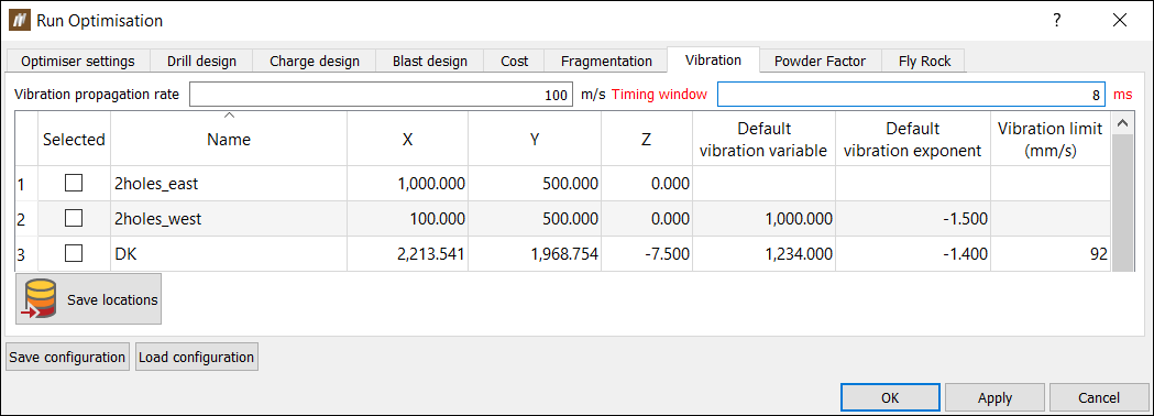
Configuring the Vibration tab
Configure the Vibration tab by completing the following settings:
-
Set the Vibration propagation rate.
-
Set the Timing window.
-
Select the Monitoring stations you would like to include as a reference by selecting the checkbox next to the appropriate monitoring station.
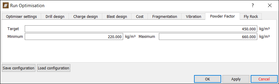
Configuring the Powder Factor tab
Configure the Powder Factor tab by completing the following settings:
-
Target — If you have set the Powder Factor to an objective, set this parameter.
-
Minimum/Maximum — If you have set the Powder Factor to a constraint, set the range you want the Powder Factor to be in by specifying the Minimum and the Maximum.
Configuring the Fly Rock tab
Configure the Fly Rock tab. Note that the BlastMCF calculates 2D fly rock projection only. Complete the settings below:
-
Fly rock model — Choose the fly rock model you want to implement from the following options: McKenzie, 2009 and Richards and Moore, 2006.
-
Fly rock parameters — Set the following parameters:
-
Factor of Safety — Provide a value that will be used to make the prediction of fly rock projection more conservative.
-
Rock density — Provide this value if you chose the McKenzie, 2009 model in the previous step.
-
K factor — Provide this experimentally derived value if you chose the Richards and Moore, 2006 model in the previous step.
-
-
Use maximum fly rock range — Select this checkbox and enter a value if you want to impose a maximum fly rock range that you don’t want the fly rock boundary to exceed.
-
Exclusion zone polygons — Drag and drop polygons from the Data Explorer into this field. The BlastMCF will exclude these polygons from the fly rock zone.

Processing input configuration
Once you have configured the targets you have selected, you can submit your inputs to the BlastMCF for processing. To generate your solution set:
-
Click OK or Apply in the bottom right corner. If there are errors with your input configuration, then they will be reported in the Report Window. Otherwise, your inputs will be packaged and sent to the BlastMCF.
-
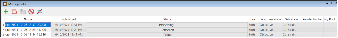
Use the Manage Jobs window to view the progress of your job. The Manage Jobs window is in the same place as the Report Window.
-
To cancel a job, select the row in the table with the job and click
 .
. -
To permanently delete a job, click
 .
. -
To add another job, click
 .
.
-
-
After the inputs have been processed, the results will be displayed. To open your results, select the row in the table with the completed job and click
 .
.
Note: Save your input configuration by clicking ![]() to open the Run Optimisation panel. Click the Save configuration button in the bottom left corner of the Run Optimisation panel. Similarly, you can load a previously saved configuration by clicking the Load configuration button next to the Save configuration button.
to open the Run Optimisation panel. Click the Save configuration button in the bottom left corner of the Run Optimisation panel. Similarly, you can load a previously saved configuration by clicking the Load configuration button next to the Save configuration button.
Interpreting the results from BlastMCF
Once you have successfully submitted your inputs, BlastMCF will generate a number of solutions. The number of solutions you generate will depend on the number of objectives and constraints:
-
1 objective (and 1 constraint) will generate 1 solution.
-
2 competing objectives will generate 15 solutions.
-
3 competing objectives will generate 8 solutions.
Note: In order for BlastMCF to properly analyse your data, it is important that you select competing objectives (see table).
These solutions can be viewed as a graph and as a table.
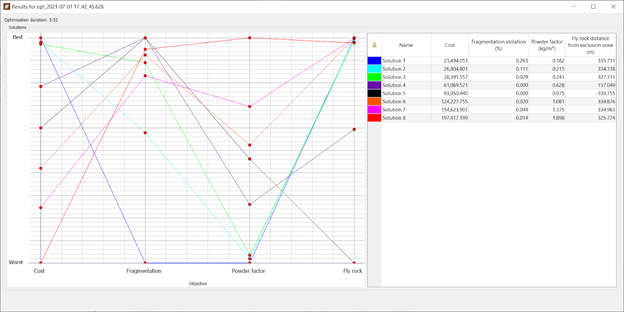
Graphing the solution set
The graph displays each solution and the optimisation of each objective.
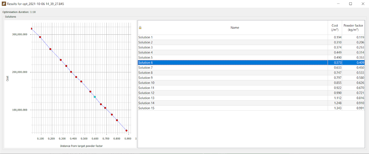
In the image below, cost and powder factor were selected as objectives. The costliest solution is closest to the set target powder factor, while the cheapest solution is furthest away from the target powder factor.
In the image below, Solution 1 was the best solution for Cost and is, therefore, highest on the Worst-Best axis in terms of Cost. It is, however, the worst solution for the other targets included. On the other hand, Solution 8 is the costliest solution, and is, therefore, the lowest on the Worst-Best axis in terms of Cost. Conversely, it has the best results for the other objectives.
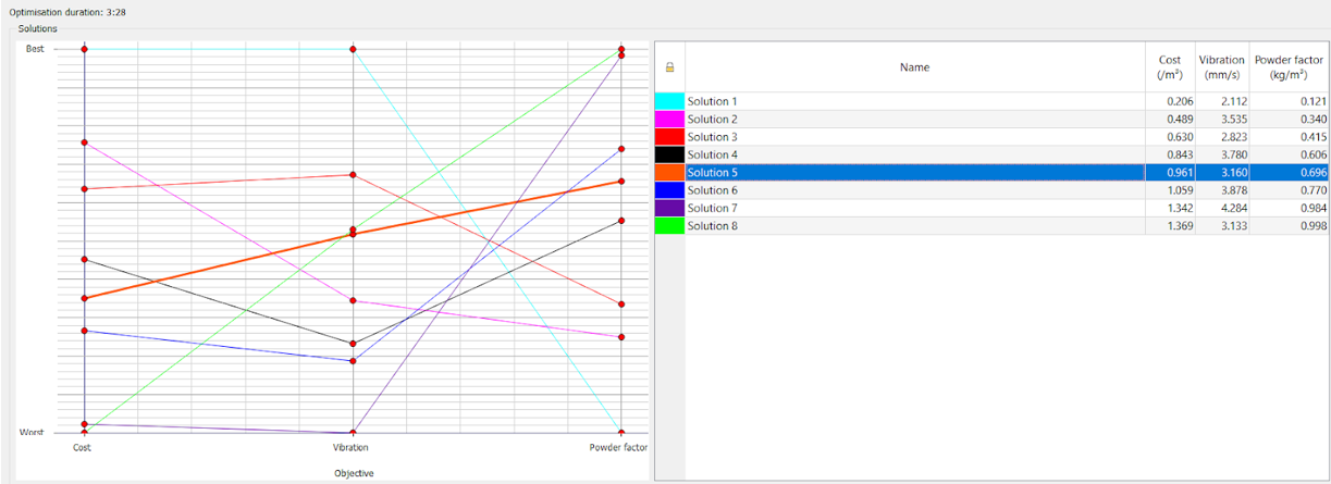
Tabulating the solution set
BlastMCF displays results for each solution per target in a table on the right-hand side of the panel. Results are ranked from cheapest to the costliest solution.
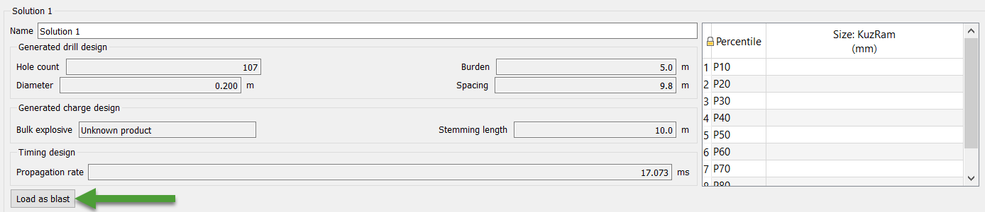
Viewing a specific solution
To view more information about a specific solution, click on the appropriate row in the table containing the solution you want to view. The added information will appear underneath the graph and the table.
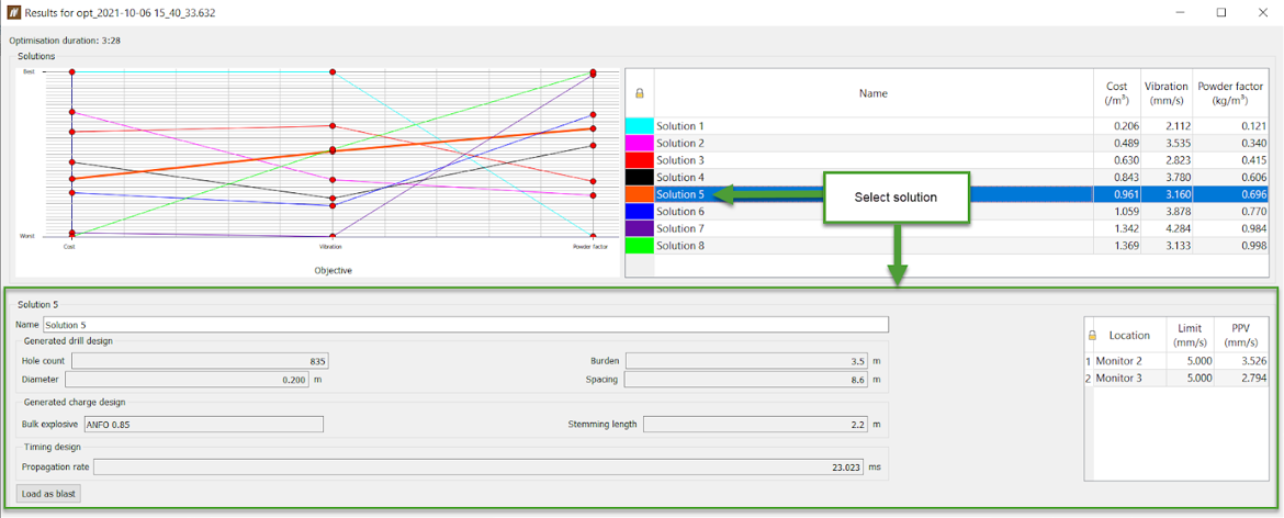
For the particular solution, BlastMCF will display objective-related information. If BlastMCF has generated a solution, that automatically means that the constraints have been met. This information is not displayed. To access this information, load the blast, and open the Hole Tabular View.
If there is no valid solution, BlastMCF will return a single solution highlighted red. The red indicates that the solution violates the set constraints.
You can load the blast into the Project Explorer by clicking Load as blast in the bottom left corner of the panel.