Fragmentation Modelling
Fragmentation Modelling provides data on the fragmentation size over the blast. To open the Fragmentation Modelling panel, load a tie-up into a view and go to Analysis ribbon > Modelling group > ![]() Fragmentation Modelling.
Fragmentation Modelling.
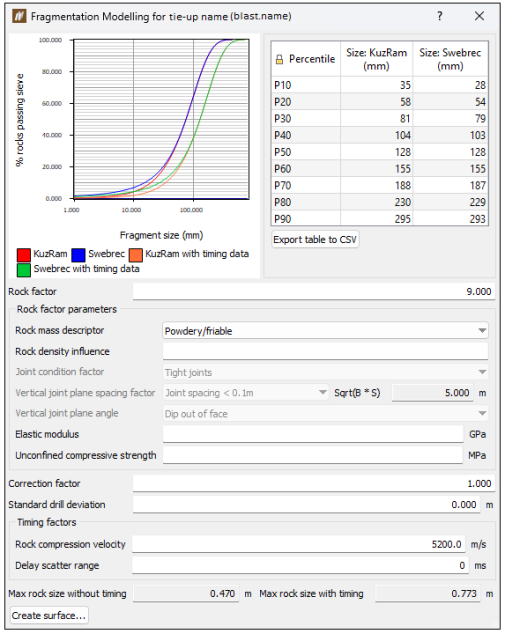
The Fragmentation Modelling panel displays an S-Curve graph with and without timing data obtained from the tie-up. A rock factor is calculated based on the rock factor parameters. On this panel, you can also specify a value for a rock factor.
Note: You can modify the shape of the S-Curve graph by altering correction factors. Timing factors also affect the timing data curves.
Estimating fragmentation
By clicking the Create surface... button, you can generate a surface that gives a visual representation of average fragmentation size over the blast. This is based on the charge energy in each hole. The fragmentation surface will be loaded in the cad container in the data explorer.
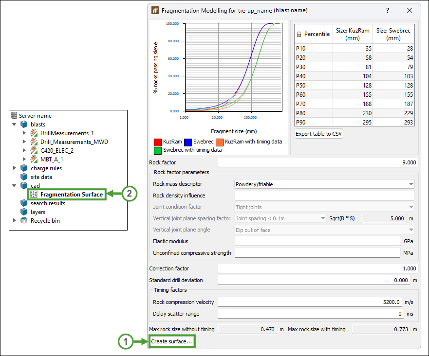
Your newly created fragmentation surface will be also directly applied to the window view:
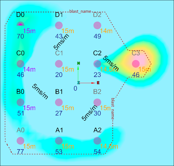
The displayed plot will provide an estimation of the expected proportions of the resulting rock fragmentation. To generate a heatmap that estimates fragmentation, the energy density of the explosive within each hole of the blast is used as a relative weighting of how much fragmentation will occur in a given area around a hole. The maximum expected rock size is shown at the bottom of the panel. If there is timing data provided (that is, the fragmentation model is generated from a tie-up and the timing factors have been set), then there will be a second set of plotted lines, showing how the currently specified tie-up is estimated to affect the fragmentation.
Note: The Swebrec © function simply acts as a replacement for the Rosin-Rammler portion of the Kuz-Ram model. The median and maximum rock sizes are still computed using the adapted Kuznetsov equation found in the Kuz-Ram model.
Note: To see the median rock fragment size as it changes over the blast, press the Create surface... button. This will create a surface in the cad container. This surface represents the median rock fragment size without timing data.
Model inputs
Fragmentation of rock depends on explosive mass and explosive timing, as well as various rock factors.
The rock factor quantifies the impact of a single rock or rock mass properties on blasting outcomes. On this panel, you can specify the following:
- Rock mass descriptor (RMD)
From the following options, select the value that best describes the condition of the rock:- Powdery/friable
- Massive formation
- Vertically jointed
- Rock density influence (RDI)
It is estimated as , where
  is the rock mass density in tonnes per cubic metre (t/m3).
 - Joint condition factor
From the following items, select the options that best describe the conditions of joints in the rock mass.- Tight joints
- Relaxed joints
- Gouge-filled joints
Note: This setting will be active only if you have selected Vertically jointed in the Rock mass descriptor.
- Vertical joint plane spacing factor (JPS)
This value is partly related to absolute spacing and partly related to the ratio of hole spacing. Select the size of the joint spacing, referencing the calculated hole spacing ratio displayed on the right side of this field.Note: This setting will be active only if you have selected Vertically jointed in the Rock mass descriptor.
- Vertical joint plane angle
Describes the angle (or orientation) of the joint. You can select the following options for this value:- Dip out of face
- Strike out of face
- Dip into face
Note: This setting will be active only if you have selected Vertically jointed in the Rock mass descriptor.
Note: Dip describes a steep dip of more than 30 degrees. The Dip out of face should be used when the extension of the joint plane from the vertical face is upwards.
- Elastic modulus (Young's modulus, E)
Also known as modulus of elasticity, it is calculated as the ratio between the axial stress and axial strain change in Gigapascals (GPa), according to the formula where .
. - Unconfined compressive strength
Also referred to as the uniaxial compressive strength (UCS), it is the most widely recognised measure of strength, deformation, and fracture characteristics of the rock. It is indicated in megapascals (MPa), and its value is determined by a standard laboratory test, which consists of loading a cylindrical sample of the rock with a diameter of 50 mm, where the length to diameter ratio is 5:2 axially, until the specimen fails. -
Correction factor
After a rock factor is entered or calculated from the parameters, a correction factor can be applied to account for specific site or pit conditions (as the rock factor alone is unable to cater for all possible values). The correction factor should be calibrated and updated once the results have been measured. -
Timing factors
These values are only applicable if the fragmentation model is being run for a tie-up. -
Rock compression velocity
The compressional stress wave velocity of the rock. This value is used to internally calculate an optimum interhole delay time, based on the optimum interhole delay time of 3-6 ms per metre burden. -
Delay scatter range
Describes the potential range of delay scatter of the initiation system. For an electronic tie-up, this value will likely be 0.Note: Entering the rock factor parameters simply updates the Rock factor value. It is a more quantifiable way to calculate the rock factor. If the rock factor is already known, it can simply be entered on its own.
