Draw
Source file: draw.htm
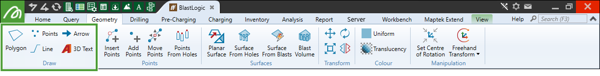
The Draw group of the Geometry ribbon contains tools that allow you to create shapes and text.
 Polygon
Polygons are closed lines or loops that you can use to define the boundaries of areas of interest. This is particularly useful when modelling, filtering or cropping data.
To create a polygon, follow these steps:
-
On the Geometry ribbon, in the Draw group, select
Polygon.A point request will appear in the status bar at the bottom of the Workbench window.

-
Click the desired points in the view window to form the polygon. BlastLogic will connect the points you click with lines in the view to display the polygon outline.
Alternatively, enter the initial desired point into the First point coordinate fields on the status bar and click
 to confirm the point. The First point label will then change to Next point that allows you to enter the next polygon point. You can continue this process until you have entered all of the desired polygon points.
Tip: Click
 in the view window toolbar to enable top view that helps you ensure the polygon you create has the intended coordinates.
 -
Press Enter or click
 to complete the polygon. BlastLogic will save the polygon to the
 cadcontainer in the project explorer.
 Points
Points can be created to manipulate or add to existing data.
-
Go to the Geometry ribbon > Draw group and select
Points. -
In the point request that appears in the status bar, enter the coordinates of the first point and click
 , or click a point in the view window to auto-fill the fields.
Tip: Initially the points will be created on the action plane. Enter a Z value to place the point in the 3D space.
- Repeat step 2 to enter as many more points as required.

- Complete the sequence by either right-clicking, clicking
 in the status bar, or pressing Enter.
The points become one object and are saved in the
cadcontainer. The tool is also reset and ready for new entries. -
When finished with the tool, click
 or press Esc to close the function.
Tip: Create points while in top view ![]() or in action plane front view
or in action plane front view ![]() .
.
 Line
Line
You can create lines to manipulate or add to existing data.
To create a line, follow these steps:
-
On the Geometry ribbon, in the Draw group, select
Line.The status bar will appear at the bottom of the view window.
-
Click the desired points in the view window to form the line. In the view window, BlastLogic will connect the points you click with lines to display the line shape.
Alternatively, enter the initial desired point into the First point coordinate fields on the status bar and select
to confirm the point. The First point label will then change to Next point that allows you to enter the next line point. You can continue this process until you have entered all of the desired line points.
Tip: Click
in the view window toolbar to enable top view that helps you ensure the line you create has the intended coordinates. -
Press Enter or click
to complete the line. BlastLogic will save the line to the cadcontainer in the project explorer.
Setting line style
You can customise the way lines are displayed by setting line styles.
To define a line style, follow these steps:
-
Go to the
cadfolder in the project explorer and open the line for which you want to define a line style. -
Right-click on the line in the view window and select
 Edit >
  Line Style... from the context menu.
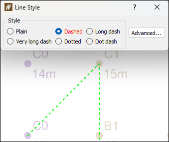
 -
Define the line style by selecting the corresponding radio button. The changed style will be directly applied in the view window.
-
Optionally, select Advanced... to further customise your line style.
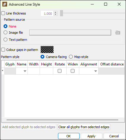
The Advanced Line Style window allows you to define the following line properties:
-
Line thickness. Select the Line thickness checkbox and move the slider to specify the required value. Alternatively, enter the value directly in the field next to the slider.
-
Pattern source. Select one of the following options to define the line pattern:
-
None: Make the line solid (i.e. no pattern).
-
Image file: Click and browse to open an image file as the basis for the line pattern.
-
Text pattern: Type a pattern in the text field.
Note: The tool produces a linear On-Off pattern along a line. Dark colours and letters equate to On, or visible segments, taking the assigned line colour. Light colours and spaces equate to Off segments or gaps between the visible segments.
-
-
Colour gaps in pattern. Select this checkbox to nominate a colour for the Off segments instead of using invisible gaps. Click the colour box to select a colour from the palette. Double-click to open the advanced Select a colour tool.
-
Pattern style. Choose the behaviour of the pattern when changing viewing angle. You can select from the following types:
-
Camera-facing means that the pattern is created from the viewpoint of the camera. This can result in the pattern appearing to slide along slightly as the camera moves around.
-
Map-style means the pattern is fixed with respect to the background, as if drawn directly onto a map. This style of pattern remains static on the background as the camera moves around.
-
-
Glyphs. Glyphs are basic shapes that can be incorporated into the line pattern. The glyph table provides a wide range of settings such as Width, Height, Rotate, Widen, Alignment and Offset distance. These allow tight control on placement of the glyphs as well as behaviour in the image, such as whether the glyphs are attached to the line or can rotate freely around the line.
Tip: You can select individual line segments using the
 (Select edges) tool and add or clear glyphs on them by selecting glyphs and clicking the appropriate Add selected glyph to selected edges button or Clear all glyphs from selected edges button.
-
-
Once you finish defining the line style, click OK or Apply to apply these settings to the line object.
 Arrow
Arrow
You can create arrows in the view window.
To create an arrow, follow these steps:
-
On the Geometry ribbon, in the Draw group, select
Arrow.The status bar will appear at the bottom of the view window.

-
Click the desired points in the view window to form the arrow. After clicking two points in the view window, BlastLogic will connect the points with an arrow.
Alternatively, enter the initial desired point into the Starting point coordinate fields on the status bar and select
to confirm the point. The Starting point label will then change to End point that allows you to enter the second arrow point.
Tip: Click
in the view window toolbar to enable top view that helps you ensure the arrow you create has the intended coordinates. -
Press Enter or click
to complete the arrow. BlastLogic will save the arrow to the cadcontainer in the project explorer.
 3D Text
The 3D Text tool allows you to create annotations. You can use these annotations in processes such as using tie-up sheets.
To create an annotation, follow these steps:
-
On the Geometry ribbon, in the Draw group, select 3D Text.
The Text Creation Tool panel will appear.
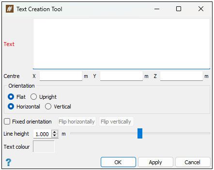
-
Enter the appropriate information into the Text and Centre fields.
-
Select the options you desire in the Orientation and Fixed orientation sections.
-
Select the height for the line and text colour with Line height and Text colour fields respectively.
-
Click OK or Apply. BlastLogic will save the text to the
cadcontainer in the project explorer.