Site
Source file: site.htm
Site
The ![]() Site tool allows you to configure your site setup, including personnel, machinery, custom properties, and colour schemes. To open the tool, navigate to the Setup group in the Home ribbon, and select
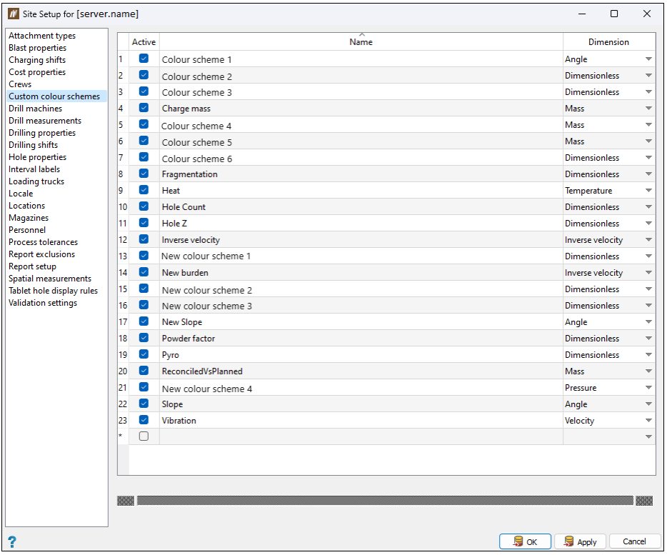
Site tool allows you to configure your site setup, including personnel, machinery, custom properties, and colour schemes. To open the tool, navigate to the Setup group in the Home ribbon, and select ![]() Site. The Site Setup panel will appear. The panel consists of the list of tabs and the workspace with fields corresponding to the selected tab.
Site. The Site Setup panel will appear. The panel consists of the list of tabs and the workspace with fields corresponding to the selected tab.
Attachment types
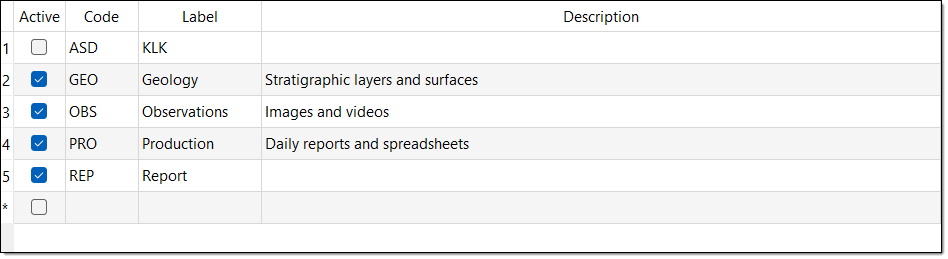
Use the Attachment types tab to create and configure different attachment types. Before publishing an attachment, you must associate it with an attachment type. In this tab, you can define these types and mark the types as active or inactive.
Creating an attachment type
To create an attachment type, select an empty row in the table and enter the required information in the Code, Label, and, optionally, Description column. Select the checkbox in the Active column to enable using this attachment type in BlastLogic. Click OK or Apply to save the applied changes.
Other operations
-
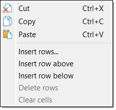
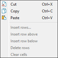
To cut, copy, or paste in the table, right-click on the desired row and select the corresponding option in the context menu.
-
To insert rows in the table, right-click on the desired row and select an insert option from the context menu.
-
To delete a row, you must first clear the checkbox in the Active column. You can then right-click on the row and select Delete rows from the context menu.
Blast properties
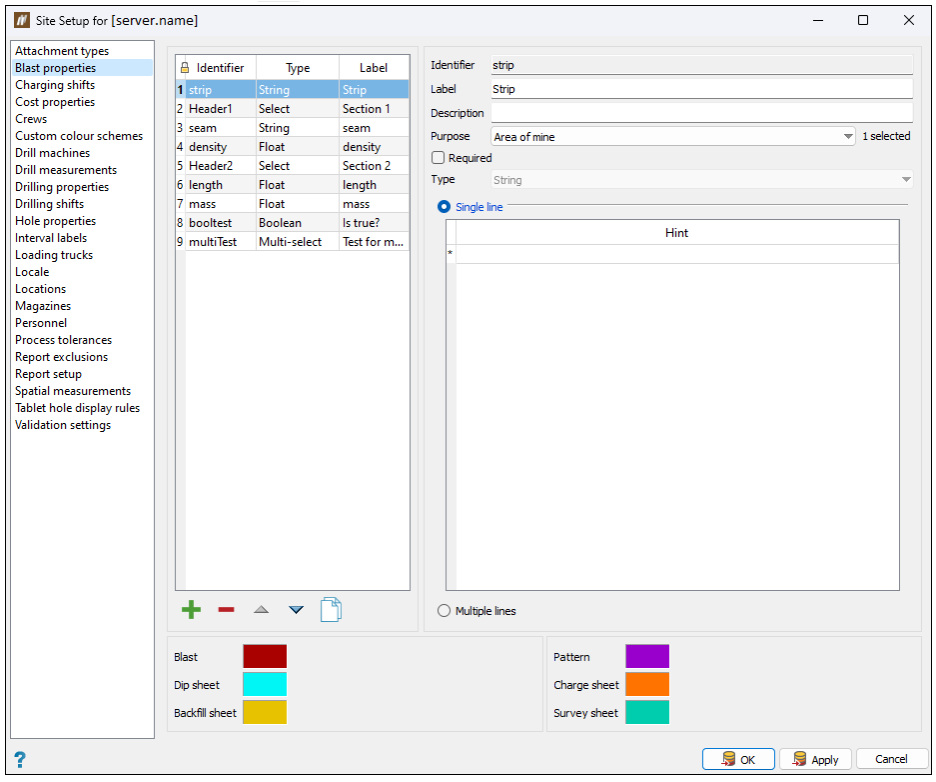
Use the Blast properties tab to define a set of custom fields specific to a blast on a particular site.
Adding custom properties
To add a custom property, follow these steps:
-
Click
 . BlastLogic will add a new property to the properties table and display the property detail fields on the right side of the panel.
 -
Enter the desired information into the Identifier, Label, and Description fields.
Note: You can enter only letters, digits and underscores into the Identifier field as BlastLogic references this name internally.
-
Select the appropriate information in the Purpose drop-down.
Note: To make the property available on the BlastLogic tablet, select Blast observation.
-
Select the Required checkbox if you wish to make the property mandatory.
-
Select the property type using the Type drop-down. There are six types to choose from in BlastLogic:
- Boolean. You can turn these types on or off via a checkbox.
-
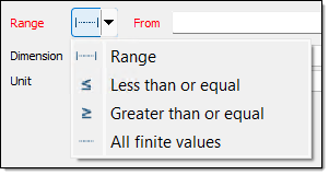
Float. These types must have a range set as greater than a given value, less than a given value, in between two values, or all values. You must also define the dimension and units of float properties.
-
Range. These types must have their dimension and units set.
-
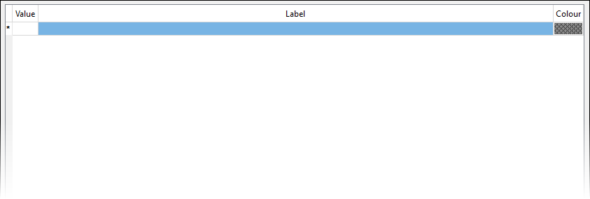
Select. This type is a field in which you can create different values to select from when entering data. You can enter these values and the associated labels in the displayed table. When entering data, you can only select one of the field values.
-
Multi-select. These fields are the same as Select fields, except you can select multiple values from the drop-down list.
-
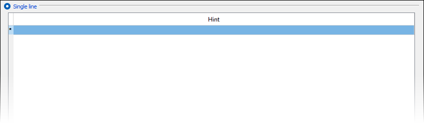
String. These types can be either a single line or a multiple line string. Single line strings can have one or more hints to store commonly entered values.
-
You can also set the following fields, depending on the selected property type:
-
Range. Set the range of the property by selecting how you wish to define the range and entering the desired values.
-
Dimension. Set the dimension using the corresponding drop-down.
-
Unit. Set the units using the corresponding drop-down.
-
Value. Set the label and colour associated with a particular value.
-
Hint. Set commonly entered values.
Optionally, select the Multiple lines radio button for a multiple line string. You cannot define hints for this option.
-
-
Optionally, edit the view boundary colours. The bottom of the panel contains the colours for each blast, pattern, or sheet boundary as displayed in the view. To edit these values, click on the colour boxes and select the desired colour from the colour picker.
-
Click OK or Apply.
Editing blast properties
To edit a blast property, follow these steps:
-
Click on a blast property in the table. BlastLogic displays the property information on the right-hand side of the panel.
-
Edit the Label and Description fields. Depending on the type of property, additional information fields may be editable.
-
Click OK or Apply.
Other operations
-
To remove a blast property, select the property and click
 .
. -
To clone a blast property, select the property and click
 .
. -
To reorder blast properties, select the property you wish to move and click the
 and
and  arrows.
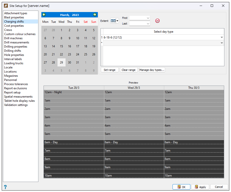
Charging shifts
Use the Charging shifts tab to configure a charging shift schedule at the start of the drill and blast life cycle.
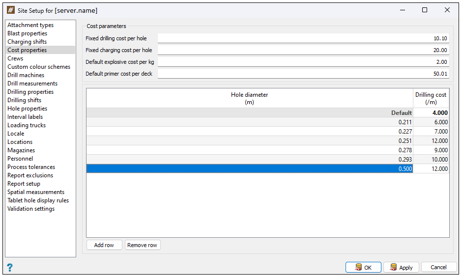
Cost properties
Use the Cost properties tab to set default parameters that you can use in cost reporting. This is beneficial if not all values are set in the Blast Product Catalogue. You can define these parameters by entering the desired values into the Cost parameter section fields.
You can also define drilling cost for different hole diameters. To do so, click the Add row button at the bottom of the table, specify the hole diameter and the drilling cost (both in units applied to your site) in the corresponding columns.
Note: BlastLogic will use the Fixed drilling cost per hole value for undefined hole diameters.
-
To cut, copy, or paste in the table, right-click on the desired row and select the corresponding option in the context menu.
-
To delete a row, select it in the table and click Remove row at the bottom of the panel.
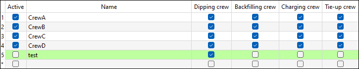
Crews
Use the Crews tab to add crews to a site and specify the scope of their activities. You can assign these crews to a combination of drill and blast operations, such as dipping, backfilling, charging, or tie-up.
-
To add a crew, enter the appropriate data into the bottom blank row of the table.
-
To edit the name of a crew, double-click on the corresponding cell in the Name column.
-
To set the appropriate jobs for a crew, select the desired table checkboxes.
-
To set a crew as active, select the corresponding crew checkbox in the Active column. Setting a crew to active will allow you to select it from the drop-down menus when entering data.
Note: Once you add a crew, you cannot remove it from a site. The given crew will not be included in your site when you deselect the checkbox that corresponds to it in the Active column. Alternatively, press Cancel to close the Site Setup panel without saving the changes you have made.
Custom colour schemes
Use the Custom colour schemes tab to edit existing colours schemes and create new ones. BlastLogic utilises colour schemes to highlight data changes in functions such as surface generation and blast modelling.
Adding custom colour schemes
To add a custom colour scheme, follow these steps:
-
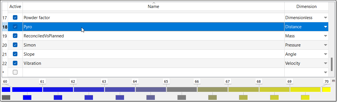
Select the Name column in the bottom empty row of the table and enter a scheme name. BlastLogic will automatically set the active checkbox in the Active column and mark the scheme as Dimensionless in the Dimension column drop-down.
-
Optionally, clear the active checkbox in the Active column if you do not wish to use the scheme.
-
Select the desired dimensions in the Dimension column drop-down.
-
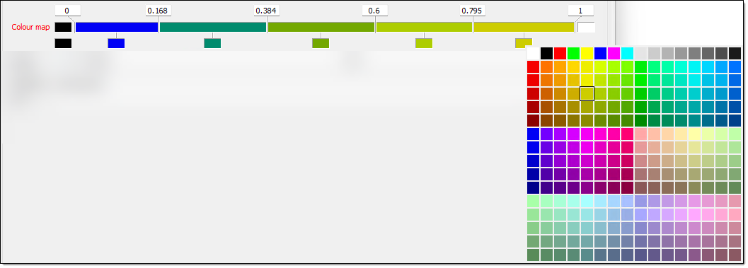
To set the interval and colours in the colour map, follow these steps:
-
Set the minimum and maximum boundary fields. By default, BlastLogic sets these fields to
0and10respectively. -
Set the additional boundaries.
-
Right-click on the colour band. The following context menu will appear.
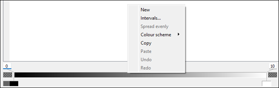
-
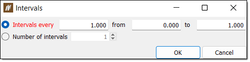
Select Intervals.... The Intervals panel will appear.
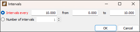
-
Select either Intervals every or Number of intervals using the corresponding radio buttons.
-
Enter the desired intervals.
-
For Intervals every, enter the space between intervals along with the start and end points in the associated fields.
-
For Number of intervals, enter the number of intervals in the associated field.
-
-
Click OK.
-
Move the mouse to the edge of the colour band such that the cursor changes to a horizontal resize cursor and click.

-
Drag the cursor to the desired boundary position. Continue this process until you have defined the necessary boundaries.

-
Set the boundary colours. You can do this in either of the following ways:
-
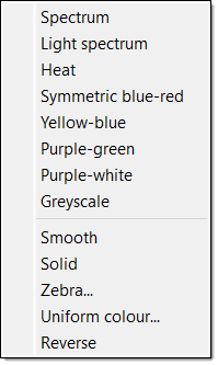
Right-click on the colour band and hover over the Colour scheme option in the context menu. Select the desired colour scheme from the list.
-
Select the colour block corresponding to a boundary and select the desired colour from the colour palette.
-
 Expand for an alternative boundary setting method.
You can also use the following method to set additional boundaries:
Click above a boundary to delete it.
 -
-
Click OK or Apply.
Other operations
-
To cut, copy, or paste in the table, right-click on the desired row and select the corresponding option in the context menu.
-
To insert rows in the table, right-click on the desired row and select an insert option from the context menu.
-
To delete a row, you must first clear the checkbox in the Active column. You can then right-click on the row and select Delete rows from the context menu.
Drill machines
Use the Drill machines tab to define a list of drill machines. BlastLogic displays these machines in the drill machine drop-down menu during data entry.
-
To add a new machine, enter the appropriate data into the bottom blank line of the table.
-
To edit the name of a machine, double-click on the corresponding cell in the Name column.
-
To set a machine to active, select the corresponding checkbox in the Active column. Setting a machine to active will allow you to select it from the drop-down menu during data entry.
-
To set a machine to inactive, deselect the corresponding checkbox in the Active column.
Drill measurements
Use the Drill measurements tab to define measure while drilling (MWD) downhole data. This tab contains predefined and editable variables, and allows you to add new, customised data categories.

Adding custom categories
To add a drill measurement custom category, follow these steps:
-
Click
. BlastLogic will add a new parameter to the table and open the parameter detail fields on the right side of the panel. -
Enter the desired information into the Identifier, Label and Description fields.
Note: You can enter only letters, digits and underscores into the Identifier field as BlastLogic references this name internally.
-
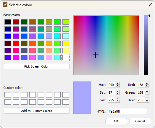
Set a colour for the property by clicking on the Colour box field and selecting a colour from the drop-down palette.
Double-click the Colour box field to open Select a colour window with detailed colour settings.
-
Select the property type using the Type drop-down. There are five types to choose from, as follows:
-
Boolean
This property represents true and false values. You can turn this type on or off via a checkbox.
-
Float
This property represents continuous numbers, thus it must have a range set as greater than a given value, less than a given value, in between two values, or all values. When defining float properties, you must also define their dimensions and units.
-
Select
This type is a field in which you can create different values to select from during data entry. You can enter these values and associated labels in the displayed table. During data entry, you can only select one of the field values.
-
Multi-select
This type is the same as Select property, but it allows you to select multiple values from the drop-down list.
-
String
This type can be either a single line or a multiple line string. Single line strings can have one or more hints to store commonly entered values.
-
-
You can also set the following fields, depending on the selected type:
Colour map Set your customised colour map. Expand for details on how to configure a custom colour map.Set the minimum and maximum boundary fields. The default minimum and maximum are set to
0and1respectively.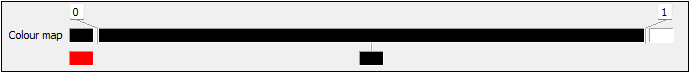
Set the additional boundaries.
Right-click on the colour band. The following context menu will appear.
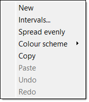
Select Intervals.... The Intervals panel will appear.
Select either Intervals every or Number of intervals using the corresponding radio buttons.
Enter the desired intervals.
For Intervals every, enter the space between intervals along with the starting and end points in the associated fields.
For Number of intervals, enter the number of intervals in the associated field.
Click OK.
Expand for an alternative boundary setting method.You can also use the following method to set additional boundaries:
Move the mouse to the edge of the colour band (such that the cursor changes to a horizontal resize cursor) and click.
Drag the cursor to the desired boundary position. Continue this process until you have defined the necessary boundaries.
Click above a boundary to delete it.Set the boundary colours. You can do this in either of the following ways:
Right-click on the colour band and hover over the Colour scheme option in the context menu. Select the desired colour scheme from the list.
Select the colour block corresponding to a boundary and select the desired colour from the colour palette.
Range Set the range of the property by selecting how you wish to define the range and entering the desired values. Dimension Set the dimension using the corresponding drop-down. Unit Set the units using the corresponding drop-down. Value Set the label and colour associated with a particular value. Hint Set commonly entered values. Optionally, select the Multiple lines radio button for a multiple line string. You cannot define hints for this option.
-
Click OK or Apply.
Editing drill measurement categories
Follow these steps to edit a drill measurement category:
-
Click on a measurement category in the table. BlastLogic will display the category information on the right-hand side of the panel.
-
Edit the desired fields. Depending on the category type, certain information fields may not be editable.
-
Click OK or Apply.
Other operations
-
To remove a drill measurement category, select the category and click
. -
To clone a drill measurement category, select the category and click
. -
To reorder the drill measurement categories, select the category you wish to move and click the
and buttons.
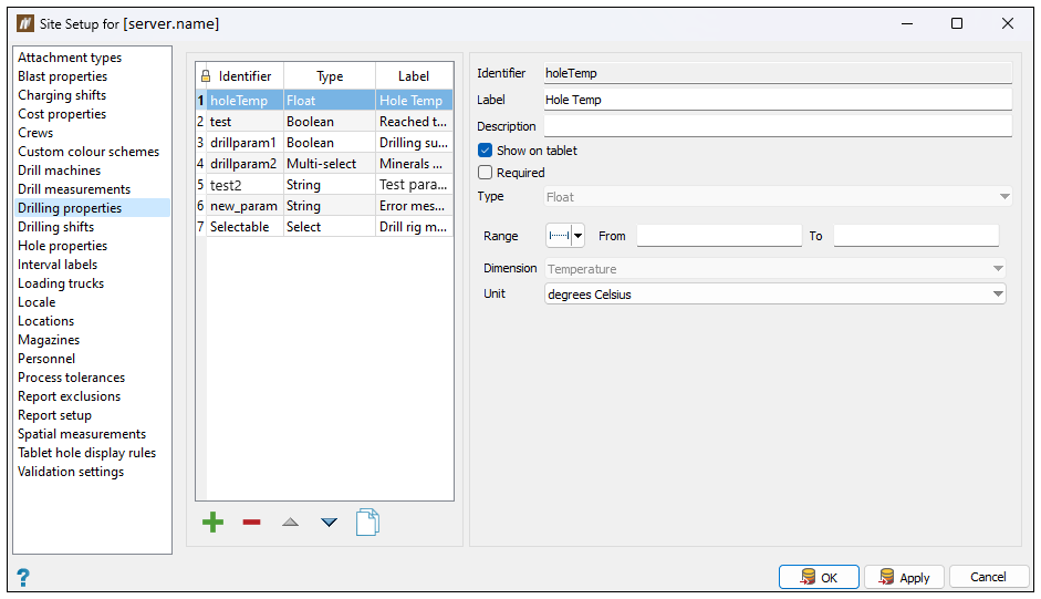
Drilling properties
Use the Drilling properties tab to create and configure custom drilling properties.
Adding custom properties
To add a custom property, follow these steps:
-
Click
. BlastLogic will add the new property to the properties table and open the property detail fields on the right side of the panel. -
Enter the desired information into the Identifier, Label and Description fields.
Note: You can enter only letters, digits and underscores into the Identifier field as BlastLogic references this name internally.
-
Select the Show on tablet checkbox if you wish to display this property on the BlastLogic tablet.
-
Select the Required checkbox if you wish to make the property mandatory.
-
Select the property type using the Type drop-down. There are six types to choose from in BlastLogic:
- Boolean. You can turn these types on or off via a checkbox.
-
Float. These types must have a range set as greater than a given value, less than a given value, in between two values, or all values. You must also define the dimension and units of float properties.
-
Select. This type is a field in which you can create different values to select from when entering data. You can enter these values and an associated labels in the displayed table. During data entry, you can only select one of the field values.
-
Multi-select. These fields are the same as Select fields, except you can select multiple values from the drop-down list.
-
String. These types can be either a single line or a multiple line string. Single line strings can have one or more hints to store commonly entered values.
-
You can also set the following fields, depending on the selected type:
-
Range. Set the range of the property by selecting how you wish to define the range and entering the desired values.
-
Dimension. Set the dimension using the corresponding drop-down.
-
Unit. Set the units using the corresponding drop-down.
-
Value. Set the label and colour associated with a particular value.
-
Hint. Set commonly entered values.
Optionally, select the Multiple lines radio button for a multiple line string. You cannot define hints for this option.
-
-
Click OK or Apply.
Editing drilling properties
Follow these steps to edit a drilling property:
-
Click on a drilling property in the table. BlastLogic displays the property information on the right-hand side of the panel.
-
Edit the Label and Description fields. Depending on the category type, additional information fields may be editable.
-
Click OK or Apply.
Other operations
-
To remove a drilling property, select the property and click
. -
To clone a drilling property, select the property and click
. -
To reorder the drilling properties, select the property you wish to move and click the
and buttons.
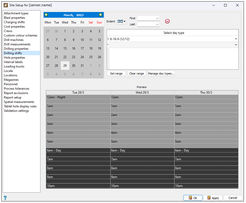
Drilling shifts
Use the Drilling shifts tab to configure a drilling shift schedule at the start of the drill and blast lifecycle.
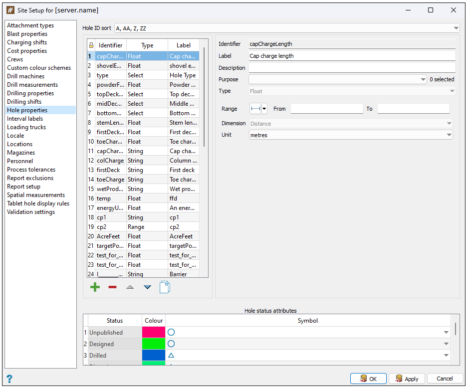
Hole properties
Use the Hole properties tab to create and configure custom hole properties.
Adding custom properties
To add a custom property, follow these steps:
-
Click
. BlastLogic adds the new property to the properties table and opens the property detail fields on the right side of the panel. -
Enter the desired information into the Identifier, Label and Description fields.
Note: You can enter only letters, digits and underscores into the Identifier field as BlastLogic references this name internally.
-
From the Purpose drop-down, select the tablet modules in which you wish to display the property. You can select the following modules:
-
Drill observations
-
Dip observations
-
Backfill observations
-
Charge observations
-
Blast observations
-
-
Select the property type using the Type drop-down. There are six types to choose from in BlastLogic:
- Boolean. You can turn these types on or off via a checkbox.
-
Float. These types must have a range set as greater than a given value, less than a given value, in between two values, or all values. You must also define the dimension and units of float properties.
-
Multi-select. These fields are the same as Select fields, except you can select multiple values from the drop-down list.
-
Range. These types must have their dimension and units set.
-
Select. This type is a field in which you can create different values to select from during data entry. You can enter these values and an associated labels in the displayed table. During data entry, you can only select one of the field values.
-
String. These types can be either a single line or a multiple line string. Single line strings can have one or more hints to store commonly entered values.
-
You can also set the following fields, depending on the selected type:
-
Range. Set the range of the property by selecting how you wish to define the range and entering the desired values.
-
Dimension. Set the dimension using the corresponding drop-down.
-
Unit. Set the units using the corresponding drop-down.
-
Value. Set the label and colour associated with a particular value.
-
Hint. Set commonly entered values.
Optionally, select the Multiple lines radio button for a multiple line string. You cannot define hints for this option.
-
-
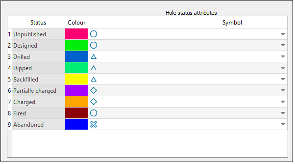
Optionally, edit the hole status colours and attributes. The bottom of the panel contains the colours and symbols for each hole status as displayed in the view. To edit these, click on the colour or shape cells and select the desired colour or shape from the drop-down.
-
Click OK or Apply.
Editing hole properties
To edit a hole property, follow these steps:
-
Click on a hole property in the table. BlastLogic will display the property information on the right-hand side of the panel.
-
Edit the Label and Description fields. Depending on the type of property, additional information fields may be editable.
-
Click OK or Apply.
Other operations
-
To remove a hole property, select the property and click
. -
To clone a hole property, select the property and click
. -
To reorder the hole properties, select the property you wish to move and click the
and buttons.
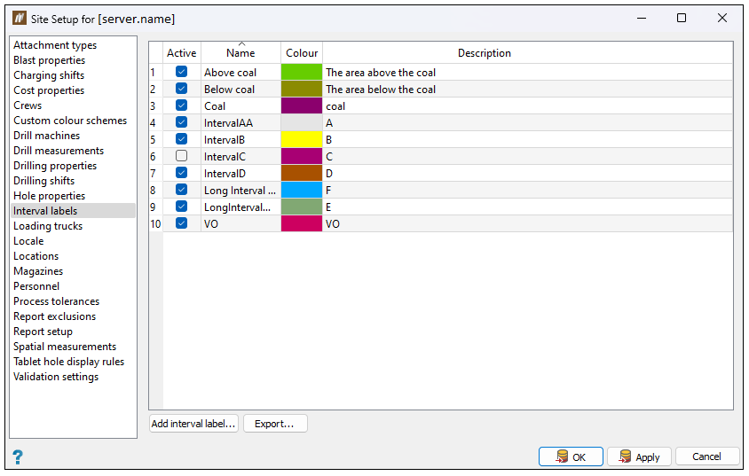
Interval labels
Use the Interval labels tab to define interval labels. You can select from these labels when defining intervals for objects.
Note: Once you add an interval, you cannot remove it from your site. The given interval will not be included in your site when you deselect the checkbox that corresponds to it in the Active column. Alternatively, press Cancel to close the Site Setup panel without saving the changes you have made.
Adding a custom interval label
Follow these steps to add a custom interval label:
-
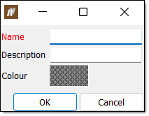
Click the Add interval label... button. The following panel will appear:
-
Enter the appropriate information into the Name and Description fields.
-
Click the Colour field and select the desired label colour from the drop-down colour palette.
-
Click OK. BlastLogic will add the label to the panel table and automatically select the checkbox in the Active column.
-
Optionally, clear the checkbox in the Active column if you do not wish to use the label.
-
Click OK or Apply.
Other operations
-
To cut, copy, or paste in the table, right-click on the desired row and select the corresponding option in the context menu.
-
To export a label, select the desired label and click Export.... The file explorer will appear, allowing you to select a location to save the label. Click OK to export the label.
Loading trucks
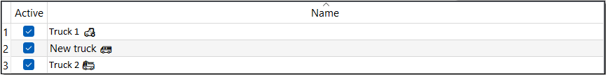
The Loading trucks tab allows you to define a list of loading trucks. BlastLogic displays the trucks in the drop-down menus during data entry.
-
To add a new truck, enter the appropriate data into the bottom blank row of the table.
-
To edit the name of a truck, double-click on the corresponding cell in the Name column.
-
To set a truck to active, select the corresponding checkbox in the Active column. Setting a truck to active will allow you to select the truck from the drop-down menus during data entry.
-
To set a truck to inactive, deselect the corresponding checkbox in the Active column.
Locale
Use the Locale tab to select the time zone that the drill and blast operations will be conducted in.
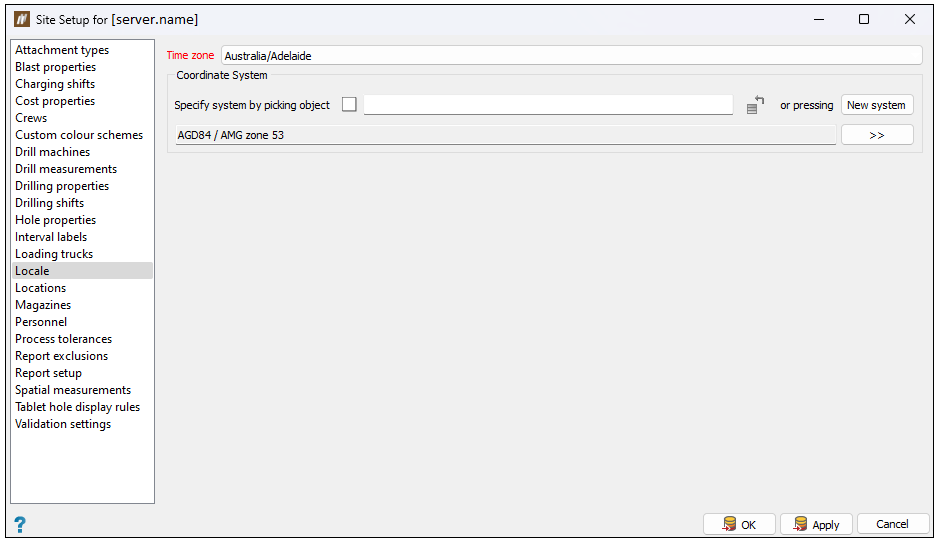
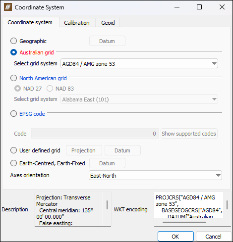
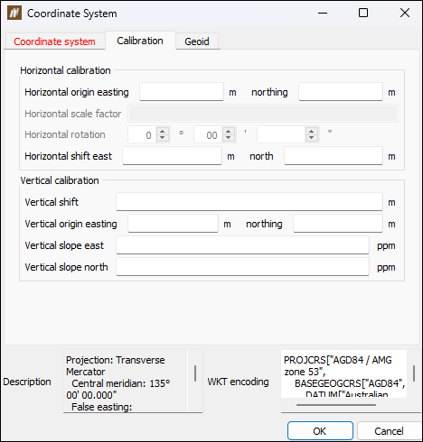
You can provide BlastLogic with additional information regarding the coordinate system by clicking theNew System button. This will open the Coordinate System panel that consists of the following tabs:
-
Coordinate system, where you can select the grid type to be applied to your site and the orientation of axes to be displayed in BlastLogic.
-
Calibration, where you can set the horizontal and vertical calibration.
-
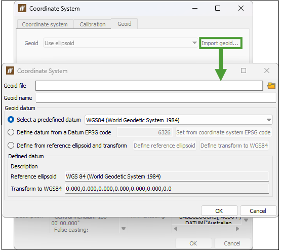
Geoid, where you can import a geoid file into BlastLogic. To do so, click the Import geoid... button and select the required file in the Coordinate System panel. After entering the required information in the Geoid name, Geoid datum, and Defined datum fields, click OK to apply it in BlastLogic.
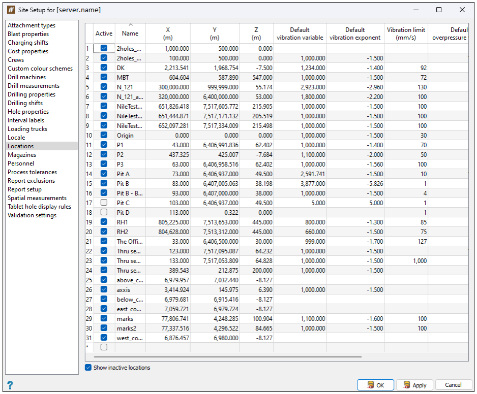
Locations
Use the Locations tab to create monitoring stations at specific locations for vibration and overpressure analysis.
Note: Once you add a location, you cannot remove it from your site. The given location will not be included in your site when you deselect the checkbox that corresponds to it in the Active column. Alternatively, press Cancel to close the Site Setup panel without saving the changes you have made.
-
To add a location, enter the appropriate data into the bottom blank row of the table.
-
To edit the name of a location, double-click on the corresponding cell in the Name column.
-
To set the details of a location, enter the appropriate information into the variable table columns.
-
To set a location as active, select the corresponding location checkbox in the Active column. Setting a location to active will allow you to select the location from the drop-down menus during data entry.
-
To set a location as inactive, deselect the corresponding location checkbox in the Active column.
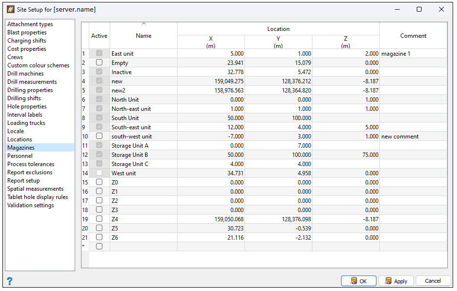
Magazines
Magazines are storage sites for blast products. Use the Magazines tab to add magazines to your site.
Note: Once you add a magazine, you cannot remove it from your site. The given magazine will not be included in your site when you deselect the checkbox that corresponds to it in the Active column. Alternatively, press Cancel to close the Site Setup panel without saving the changes you have made.
-
To add a magazine, enter the appropriate data into the bottom blank line of the table.
-
To edit the name of a magazine, double-click on the corresponding cell in the Name column.
-
To set the details of a magazine, enter the appropriate information into the Location and Comments table columns.
-
To set a magazine as active, select the corresponding magazine checkbox in the Active column. Setting a magazine to active will allow you to select the magazine from the drop-down menus during data entry.
-
To set a magazine as inactive, deselect the corresponding magazine checkbox in the Active column, corresponding to the magazine.
Note: Once you create and add stock to a magazine, you cannot make it inactive.
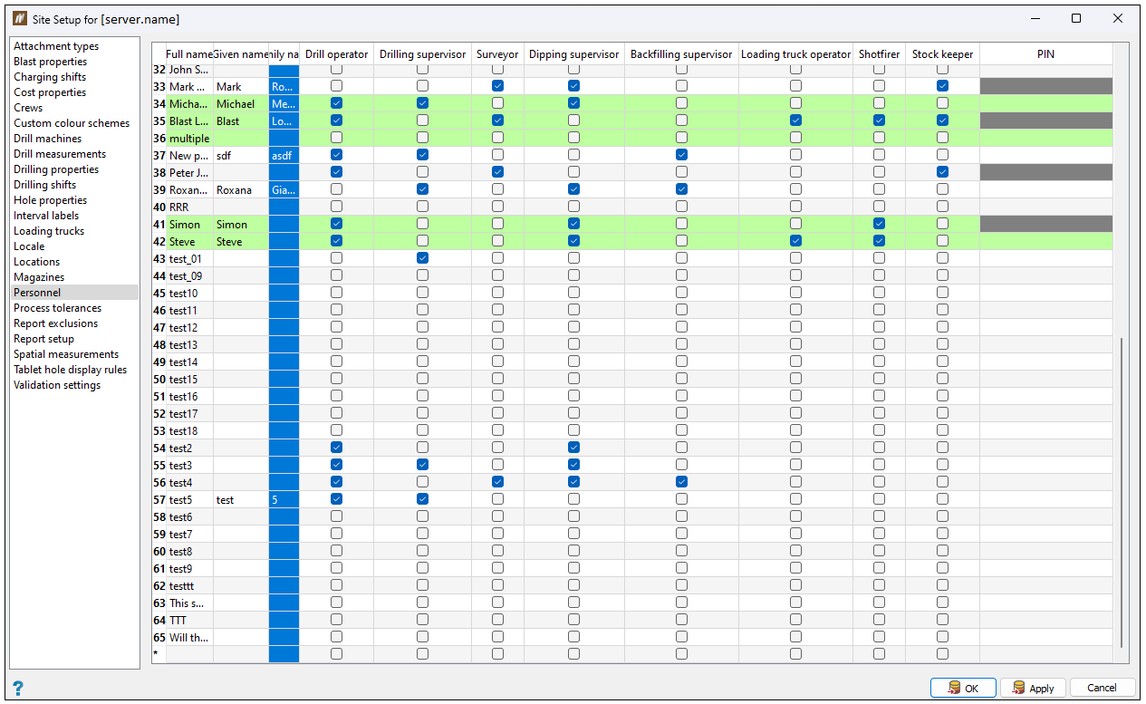
Personnel
Use the Personnel tab to add operators, surveyors, supervisors, shotfirers, and stock keepers to your setup.
Note: Once you add a personnel item, you cannot remove it from to the table. You can make a person inactive by deselecting all checkboxes corresponding to the assigned roles. Alternatively, press Cancel to close the Site Setup panel without saving the changes you have made.
-
To add new personnel, enter the appropriate data into the bottom blank row of the table.
-
To edit the name of personnel, double-click on the corresponding cell in the Full Name column.
-
To set the appropriate roles for the personnel, select the desired table checkboxes.
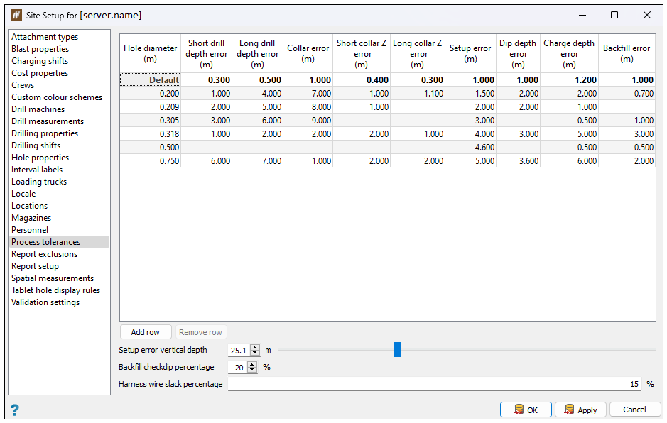
Process tolerances
Use the Process tolerances tab to set process tolerances per hole diameter. BlastLogic will use the Default value for any undefined hole diameters.
During the design of a blast, idealised or vacuum conditions are in place. When you first introduce real world data to the setup, BlastLogic adjusts the design data to establish a point of reference. As you update the data in the setup, this data is compared with the point of reference (design) data.
A process tolerance defines an acceptable range for the new data to deviate from the design data. You can view these tolerances during drill validation and when generating reports. If the tolerance is exceeded, BlastLogic will notify the drill and blast engineer that the necessary action should be taken.
Adding a tolerance
Follow these steps to add a tolerance:
-
Select Add row. BlastLogic will add a new row to the table.
-
Select each cell in the row and enter the desired information.
Expand for more information on the per hole diameter tolerances.
You can define values for the following:
Term Definition Reports Short drill depth error The maximum tolerated difference between the target drill depth and the as-drilled depth, if the as-drilled drill depth is shorter than expected. If the error exceeds the limit set, BlastLogic will highlight the corresponding cell in red in the Validate Drilling table. -
Drill Depth Accuracy report
Long drill depth error The maximum tolerated difference between the target drill depth and the as-drilled depth, if the as-drilled drill depth is longer than expected. If the error exceeds the limit set, BlastLogic will highlight the corresponding cell in red in the Validate Drilling table. -
Drill Depth Accuracy report
Collar error The maximum tolerated difference between the as-drilled collar and the design drill collar. BlastLogic only considers the X and Y axes. If the error exceeds the limit set, BlastLogic will highlight the corresponding cell in red in the Validate Drilling table. -
Drill Collar Accuracy report
Short collar Z error The maximum tolerated difference between the as-drilled collar Z value and the design collar Z value, if the as-drilled collar Z value is less than the design collar Z value. If the error exceeds the limit set, BlastLogic will highlight the corresponding cell in red in the Validate Drilling table. N/A Long collar Z error The maximum tolerated difference between the as-drilled collar Z value and the design collar Z value, if the as-drilled collar Z value is greater than the design collar Z value. If the error exceeds the limit set, BlastLogic will highlight the corresponding cell in red in the Validate Drilling table. N/A Setup error The measurement of the error resulting from angle and bearing. The error is measured by placing the design and as-drilled hole in the same XYZ position (which removes the influence of XY and Z error), and using the user-defined depth (see Setup error vertical depth below). This allows the measurement of the horizontal distance between the design and as-drilled holes. The obtained distance value is solely based on the angle and bearing change, which can be then used as an error value and compared to the defined tolerance values. -
Drilling Setup Accuracy report
Dip depth error The maximum tolerated difference between the actual dip depth and the target dip depth (the previously recorded dip depth). For dip data entry, the cell is coloured in red when the recorded dip depth is more than the dip depth tolerance greater than the previous known depth. N/A Charge depth error The maximum tolerated difference between the actual charge depth (after loading charge) and the target charge depth. - Pre-charging Depth Accuracy report
- Charge Placement Accuracy report
- Pattern Condition report
Backfill error The maximum tolerated difference between the dip depth after backfilling and the target charge depth. -
Backfill Compliance report
You can view the Validate Drilling panel by navigating to the Drilling ribbon and selecting
 Validate Drilling. In this panel, open the Validation tab to view the tolerances. For more information on this tool, see the Validation page.
 -
-
Click OK or Apply.
Other operations
-
To remove a tolerance row, select the row and click Remove row.
-
To set per holes process tolerances, you can enter the desired information into the Setup error vertical depth, Backfill checkdip percentage and Harness wire slack percentage fields.
Expand for more information on the per hole tolerances.
You can define values for the following:
Report exclusions
Use the Report exclusions tab to define filters to exclude holes that do not meet certain criteria from reports.
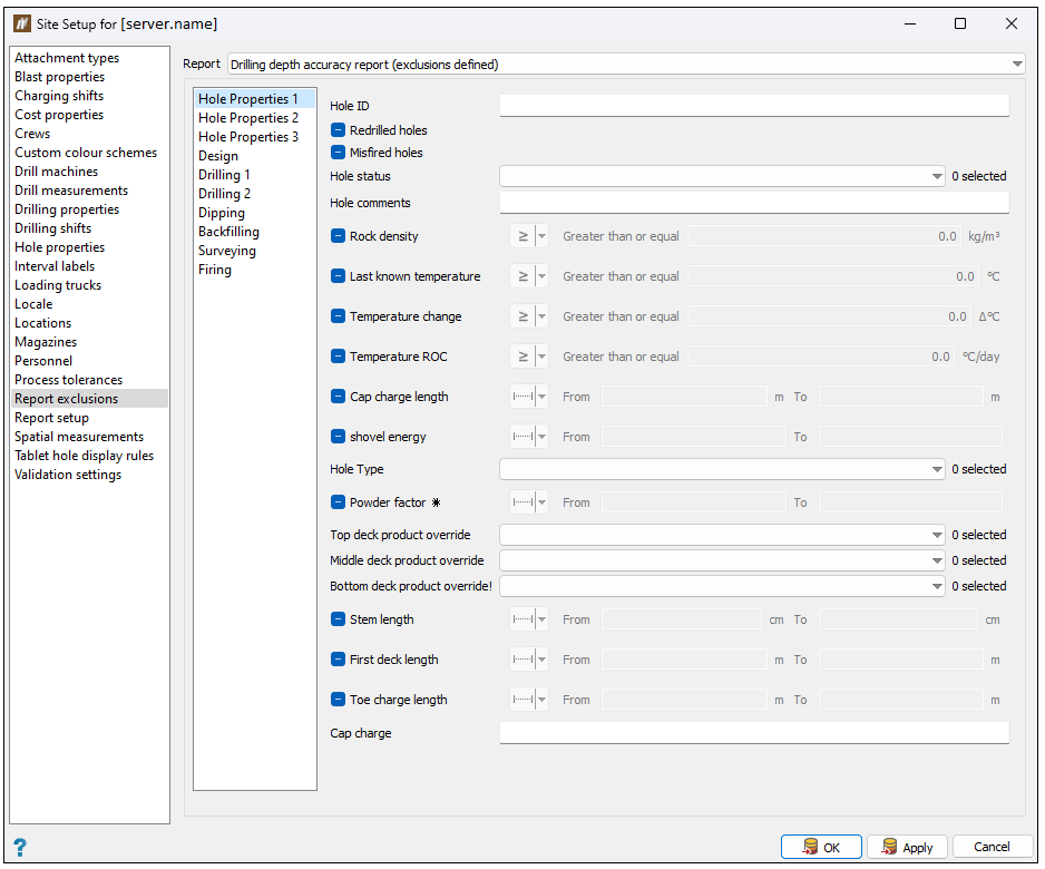
Follow these steps to define the report exclusions filters:
-
Select the report you wish to configure from the Report drop-down.
-
Select the type of properties you wish to filter using the side navigation bar.
-
Use the property checkboxes and field to exclude certain holes.
All of the checkboxes have the following three states:

Do not filter these criteria 
Filter these criteria with the entered values 
Filter for instances of these criteria that are undefined (do not have values entered) -
Click OK or Apply.
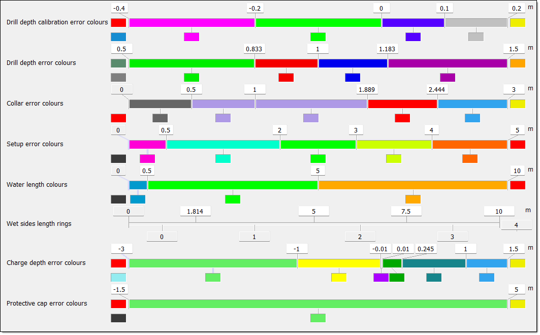
Report setup
Use the Report setup tab to define the colours and boundaries of report histograms. You can generate these reports via the Report ribbon.
To set the colours and intervals, follow these steps:
-
Set the minimum and maximum boundary fields. By default, BlastLogic sets these fields to
0and1respectively. -
Set the additional boundaries.
-
Right-click on the colour band. The following context menu will appear.
-
Select Intervals.... The Intervals panel will appear.
-
Select either Intervals every or Number of intervals using the corresponding radio buttons.
-
Enter the desired intervals.
- For Intervals every, enter the space between intervals along with the start and end points in the associated fields.
- For Number of intervals, enter the number of intervals in the associated field.
-
Click OK.
-
Move the mouse to the edge of the colour band such that the cursor changes to a horizontal resize cursor and click.
-
Drag the cursor to the desired boundary position. Continue this process until you have defined the necessary boundaries.
Expand for an alternative method of setting the interval boundaries.
You can also use the following method to set additional boundaries:
Click above a boundary to delete it. -
-
Set the boundary colours. You can do this in either of the following ways:
-
Right-click on the colour band and hover over the Colour scheme option in the context menu. Select the desired colour scheme from the list.
-
Select the colour block corresponding to a boundary and select the desired colour from the colour picker.
-
-
Click OK or Apply.
Spatial measurements
Use the Spatial Measurements tab to define custom spatial measurement properties. You can then define and query these spatial measurements for certain objects. You can also copy these measurements to custom hole properties based on an inverse distance procedure.
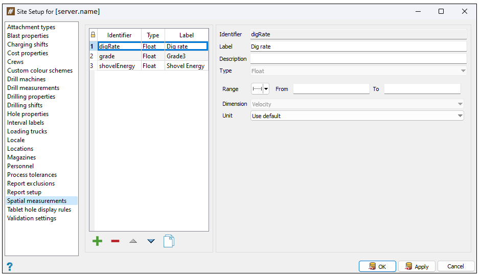
Adding custom properties
To add a custom property, follow these steps:
-
Click
. BlastLogic will give the new property default names in the Identifier and Label fields. -
Enter the desired information into the Identifier, Label and Description fields.
Note: You can enter only letters, digits and underscores into the Identifier field as BlastLogic references this name internally.
-
Select the property type using the Type drop-down.
-
Configure the following options:
-
Range. Set the range of the property by selecting how you wish to define the range and entering the desired values.
-
Dimension. Set the dimension using the corresponding drop-down.
-
Unit. Set the unit using the corresponding drop-down.
-
-
Click OK or Apply.
Editing spatial measurements
To edit a spatial measurement, follow these steps:
-
Click on a measurement property in the table. BlastLogic displays the property information on the right-hand side of the panel.
-
Edit the Label and Description fields.
Note: To preserve existing data, the remaining custom property fields are not editable.
-
Click OK or Apply.
Other operations
-
To remove a spatial measurement, select the measurement and click
. -
To clone a spatial measurement, select the measurement and click
. -
To reorder the spatial measurements, select the measurement you wish to move and click the
and buttons.
Tablet hole display rules
Use the Tablet hole display rules tab to add and configure unique rules that control how BlastLogic tablet displays holes.
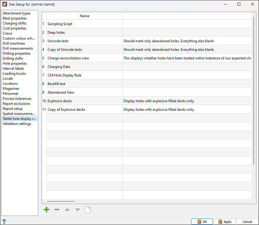
To create a hole display rule, follow these steps:
-
Click
. The Create Tablet Hole Display Rule panel will appear.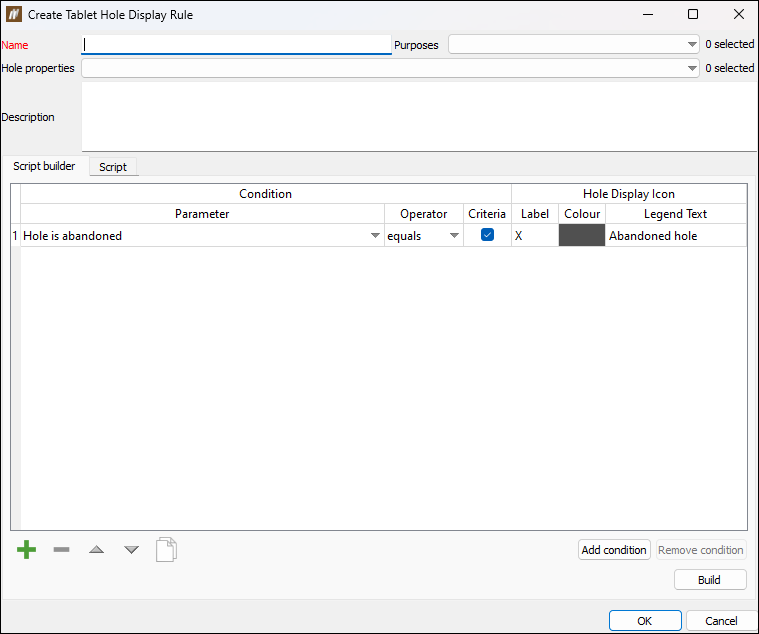
-
Enter the desired information into the Name and Description fields.
-
Specify to which tablet menus the rule should apply by selecting the required modules from the Purpose drop-down.

-
Specify custom properties to be displayed for the holes by selecting them from the Hole properties drop-down.
Note: The properties listed in the drop-down correspond to those that you have defined in the Hole properties tab in the Site Setup panel. See Hole properties for more information.
-
Create a script for the rule. The script allows you to define conditions and corresponding visualisations that BlastLogic will use to categorise the holes in the tablet view. You can do this using either of the following tabs:
-
Script builder
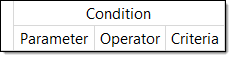
Use the Script builder tab to create table rows that form the hole display rule. Each row contains the following two sections:-
Condition. This section allows you to define the conditions of a row. These conditions provide BlastLogic with criteria to categorise the holes.
-
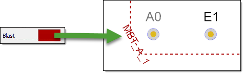
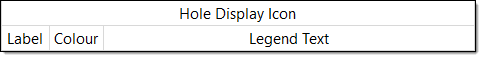
Hole Display Icon. This section allows you to define the label, colour and text BlastLogic will assign to a hole, if the hole meets the corresponding row conditions.
Expand for information on creating conditions using the script builder.
-
To create conditions using the script builder, follow these steps:
-
Click
. BlastLogic will add a row to the table. -
Select the desired hole parameter from the Parameter column drop-down. In this drop-down, you can select one of the following hole property groups to use as a parameter:
- Hole ID
- Hole is abandoned
- Last known (depth, water length, wet sides length, temperature)
- Design
- Drilling
- Dipping
- Backfilling
- Charging
- Custom
-
Select the desired operator from the Operator column drop-down. The options in the drop-down can change depending on the parameter you define. For example, if the parameter you select is a numerical value, such as Drill design - depth, then the Operator drop-down will contain the following options:
- equals
- greater than
- greater than or equal
- less than
- less than or equal
Expand for more information on the Operator drop-down options.
The table below summarises the options provided in the Operator and Criteria drop-down lists (that follow the parameter type you select).
Parameter type Example parameter Operator drop-down options Criteria (example value) A numerical property Drill design - depth - equals
- greater than
- greater than or equal
- less than
- less than or equal
A numerical value in the following form:
5.000
A time period property Drilling - start drilled time - is before
- is after
A date and time in the following format:
26/08/2022 3:04 PM
A property that contains multiple instances for each hole Charging (reconciled) - deck quantities - any are equal to
- all are equal to
- none are equal to
- sum equals
- any are greater than or equal to
- all are greater than or equal to
- none are greater than or equal to
- sum is greater than or equal to
- any are less than or equal to
- all are less than or equal to
- none are less than or equal to
- sum is less than or equal to
A numerical value in the following form:
5.000A property containing a sequence of numbers Hole ID - contains
- does not contain
- equals
A sequence of numbers in the following form:
123
A string property Charging (loaded) - primer-loading crew names - any contain
- all contain
- none contain
- any are equal to
- all are equal to
- none are equal to
A string in the form of a name or comment:
John Smith
Abandoned due to redrill.
A boolean property Drilling - is validated - equals
Select or clear the Criteria checkbox as desired. -
Enter the desired value into the Criteria column cell.
BlastLogic will evaluate the value you enter into the Criteria column based on the option that you select from the Operator drop-down. For example, if you set the Parameter drop-down to Drill design - depth, the Operator drop-down as less than or equal to and the Criteria as
5, then a hole will meet this condition if its drill design depth is less than or equal 5 m.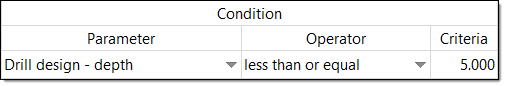
-
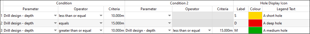
Optionally, add multiple conditions to the row. This allows you to add more detail to the rule, as a hole must satisfy all of the conditions in a row to be assigned the corresponding colour and label. To do this, follow these steps:
-
Select the desired row and click Add condition. BlastLogic will add a second condition, titled Condition 2, to the table.
BlastLogic relates two or more conditions with an AND operator. For example, if you have Condition 1 and Condition 2 in one row, BlastLogic will assign holes to that row that satisfy both these conditions.

-
Select the desired information in the Parameter and Operator drop-downs and enter the appropriate value into the Criteria cell.
-
Continue adding conditions and the appropriate information as desired.
-
-
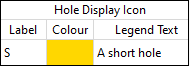
Select a colour for the label using the Colour column field. BlastLogic will colour the hole icon with this colour in the tablet view.
-
Enter the desired legend text in the Legend Text column cell. BlastLogic will display this text in the tablet view legend.
-
Add and configure additional rows by repeating these steps. Adding more rows allows you to create additional sets of conditions with corresponding colours and labels.
-
Optionally, rearrange the order of the rows by selecting the desired row and clicking the
and buttons at the bottom of the panel. BlastLogic will compare each hole to the conditions of each row, in the order that the rows appear in the table.
Important: Make sure that the conditions you want BlastLogic to check first are in the first row of the table. For example, if a hole meets the conditions of the first and second row of the rule, BlastLogic will always assign it to the first row.
-
Click Build. BlastLogic will populate the Script tab with the code for the hole display rule.
-
-
-
Script
Use the Script tab to create a hole display rule script from scratch, using the coding language JavaScript. If you need additional help creating a script, visit our support site (Maptek Support) to contact a member of our technical services team.
-
-
Click OK. BlastLogic will add the tablet hole display rule to the table.
Other operations
-
To remove a tablet hole display rule, select the rule and click
. -
To edit an existing tablet hole display rule, select Edit in the end column of the rule row.
-
To clone a tablet hole display rule, select the rule and click
. -
To reorder the tablet hole display rules, select the rule you wish to move and click the
and buttons.
Validation settings
Use the Validation settings tab to set criteria to control how users perform validation and association of drill data events and design holes. You can use either the BlastLogic Integration Service (BLIS) ( a web service that allows you to work with drill navigation systems), or the Validate Drilling panel, which is a part of the desktop application to auto-validate and associate holes (see Validate Drilling for more information).
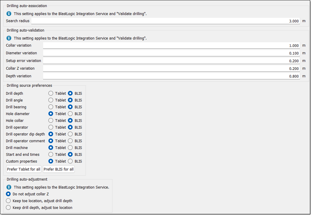
This tab contains the following sections that you can edit with the corresponding fields or radio buttons:
-
Drilling auto-association: BlastLogic will search for holes in the database with target collar values within the radius you set in the Search radius field.
-
Drilling auto-validation: BlastLogic will validate as-drilled data if it falls within the set variations.
-
Collar variation: The difference between the as-drilled and design X and Y collar values. The collar variation is usually wider than the collar error defined in the Process tolerances tab.
-
Diameter variation: The difference between the as-drilled and design diameter values.
-
Setup error variation: The difference in the as-drilled toe and design toe, if it was drilled at the standard depth.
-
Collar Z variation: The difference between the as-drilled collar Z and design collar Z. The collar Z variation is usually wider than the collar Z error defined in the Process tolerances tab.
-
Depth variation: The difference between the as-drilled depth and design drill depth.
-
-
Drilling source preferences: In this section, use the radio buttons to specify whether you wish to source different types of drilling data from the Tablet or the BlastLogic Integration System (BLIS).
-
Drilling auto-adjustment: BlastLogic automatically adjusts the as-drilled collar Z, based on the settings you select in this section. You can choose to leave the collar Z as is or adjust the toe location or drill depth, using the corresponding radio buttons.
Click OK or Apply to save these settings.
