Profile View
Source file: profile-view.htm
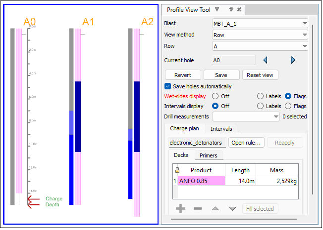
Profile view allows you to check the cross sections (side view) of holes from your blast. The cross sections are displayed along the blast's rows or echelons. Profile view visualises the charge depth, drill measurements, intervals within the hole surfaces, and shows the wet sides level of each hole. Moreover, it also provides a graphic representation of the decks and primers applied within each hole.
To use the Profile tool, follow these steps:
-
Enter profile view by clicking the
 (Profile) button in the view window toolbar. The Profile View Tool side panel will appear and the view window will display a side view of a row of holes in the blast.
 NoteBlastLogic marks the current depth and charge depth of the hole with red arrows on the ruler in the view window.
 -
Optionally, select the
 (Visualisation) tool from the view window toolbar and click the desired visualisation mode from the drop-down menu.
Note: Only Charge decks and Intervals allow for direct manipulation.
-
In the View method drop-down, select either Row or Echelon.
-
Select the desired row or echelon from the Row or Echelon drop-down.
-
Modify the hole display using the following options:
-
Wet sides display. To view the wet sides, select the Flags or Labels radio button. If you wish to turn off this view, select the Off radio button.
-
Intervals display. To view the intervals, you can select the Flags or Labels radio button. If you wish to turn off this view, select the Off radio button.
Labels Text indicating the sections within a hole that is visualised as labels next to the hole. Flags Coloured visualisations of the sections within a hole that are displayed as flags next to the hole. Wet-sides display Intervals display Default view 

Labels
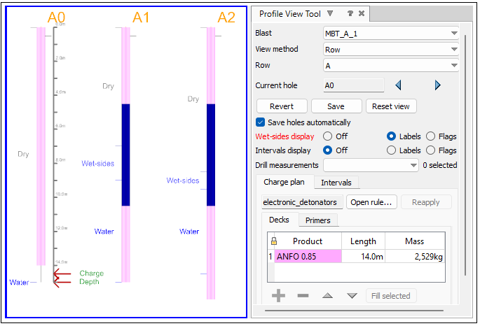

Flags

-
-
Click the
 and
and  buttons to navigate to the holes you wish to edit. The Current hole field displays the hole currently selected.
 -
From the Drill measurements drop-down menu, select the values you would like to apply in your view. The representation of these values can be specified in the Drill measurements of the Site Setup pop-up window (Home ribbon > Setup group >
 Site > Drill measurements). See Drill measurements for more information.
There are three types of properties that can be applied from this drop-down:
-
Float properties represent continuous numbers and they are displayed on the right side of the chart bars.

Note: Only one float field can be selected at a time.
-
Select properties represent user-defined parameters from the Site Setup > Drill measurements pop-up window. When selected, they are applied on the left side of the chart bars.

-
Boolean properties represent true and false values. When selected, they are applied on the left side of the chart bars.

Note: It is possible to display multiple Select and Boolean properties in the view at the same time.

Tip: To achieve better visibility, switch the Labels of Wet-sides display and Intervals display to Off while viewing drill measurements.
-
-
View or edit charge decks and intervals using the following two tabs:
-
Charge plan
The Charge plan > Primers subtab displays the primers associated with the selected holes.
The Charge plan > Decks subtab displays planned charge products in the selected holes.
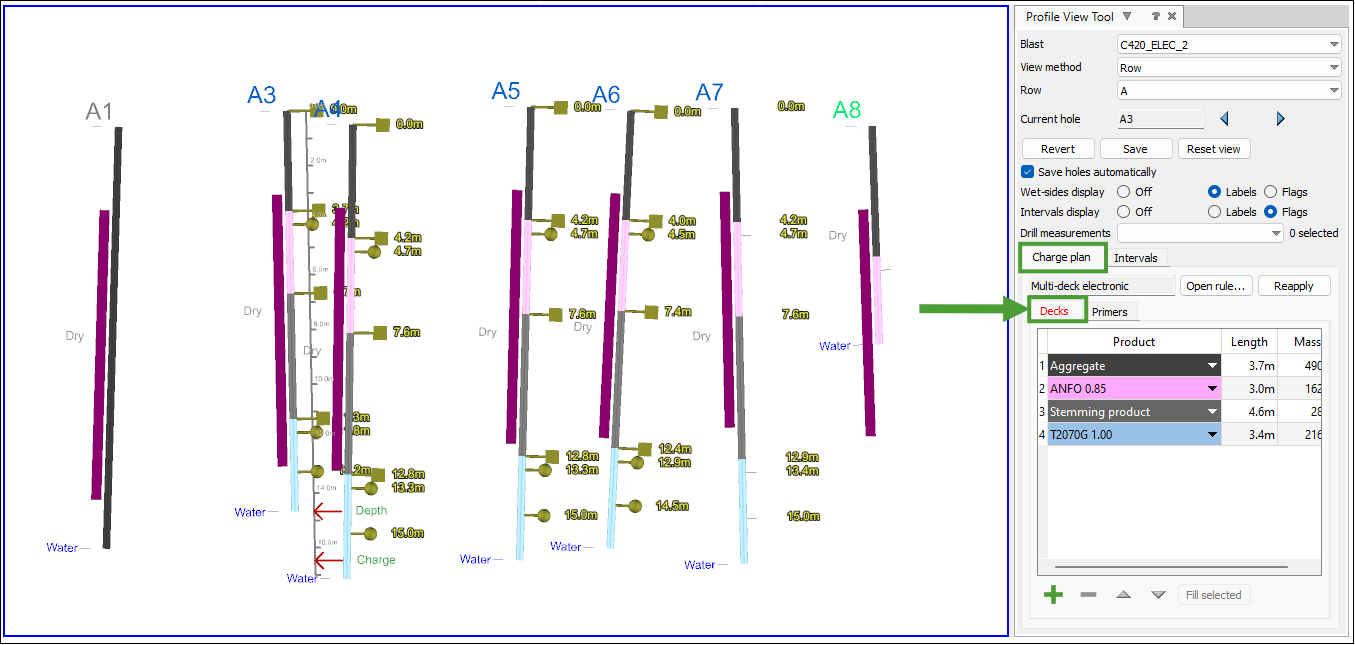
You can view the charge rule used to create this charge plan by clicking Open rule.... If any changes to the hole or charge rule are made, you can reapply the charge rule by clicking Reapply.
To modify the charge products in the Decks subtab, use the following operations:
-
To move a primer, middle mouse click the round paddle representing the primer. Hold the middle mouse button and drag the primer to its new location.
-
To modify a charge deck, middle mouse button click the square paddle representing the top or bottom of the deck. Hold the middle mouse button and drag the paddle to adjust the length of the deck.
-
To add a charge deck, press the
 button, and select the correct product from the drop-down list.
 -
To remove a charge deck, select that deck in the table and press the
 button. Alternatively, drag one of the paddles all the way to the top or bottom of the deck, effectively creating a deck length of zero. This will delete that deck from the charge plan.
 -
To modify a deck so that it adjusts its length to suit the current length of the hole, select that deck and click Fill selected. This will ensure that the selected deck is modified such that the total deck length is the same as the current hole length.
-
To move an entire deck, first change the selection mode to edge selection. Then drag a box to select the deck you wish to move. A new triangular paddle will appear. Use the middle mouse button to drag this deck to its new location.
-
-
Intervals

Note: The hole profile view automatically adds any surfaces that are linked to the holes when they are used to define hole intervals.
To modify the length of an interval, click and hold the middle mouse button on the paddle representing the top or bottom of the interval. While holding the middle mouse button, drag the paddle to its new location.

Other operations
-
To automatically save any changes, select the Save holes automatically checkbox.
-
To undo any changes made to the current holes since they were last saved, select Revert.
-
To return the view to its default orientation, select Reset view.
-
