Transform
Source file: geometry-transform.htm
The tools listed in the Transform group allow you to shift, rotate, scale and create mirror images of the objects in your view.
![]()
 Translate
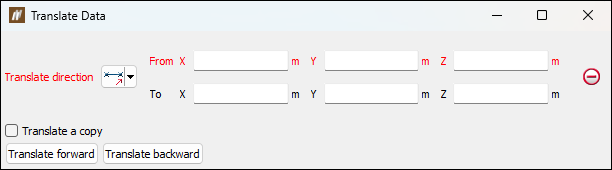
This tool allows you to translate (shift) objects in various directions.
To use it, follow these steps:
-
On the Geometry ribbon, go to the Transform group and select
Translate.
-
Select the method of defining the Translate direction from the drop-down list.
The panel will change to request additional inputs according to the selected Translate direction type. The Translate direction options are: Two points
Define the translation by specifying two points.  Two points and distance
Define the direction by specifying two points and then define the distance to translate along that direction separately.  Facet and distance
Pick as facet and then specify a distance to translate along the normal of that facet.  Axis aligned and distance
Specify an axis and how far you want to move in that direction.  Bearing, inclination and distance
Specify a bearing, inclination, and distance to translate.  Action plane axis and distance
Specify direction by choosing an axis of the current view's action plane (horizontally, vertically, or out of the action plane in its normal direction.) and then provide a distance to translate. -
Optionally, select the Translate a copy checkbox to allow you to produce a copy of the selected objects located at the nominated direction and distance from the source.
-
Select the object to be translated in the project explorer and make sure that no other objects are highlighted. In the example below, two points have been selected on the Line object from the

cadcontainer.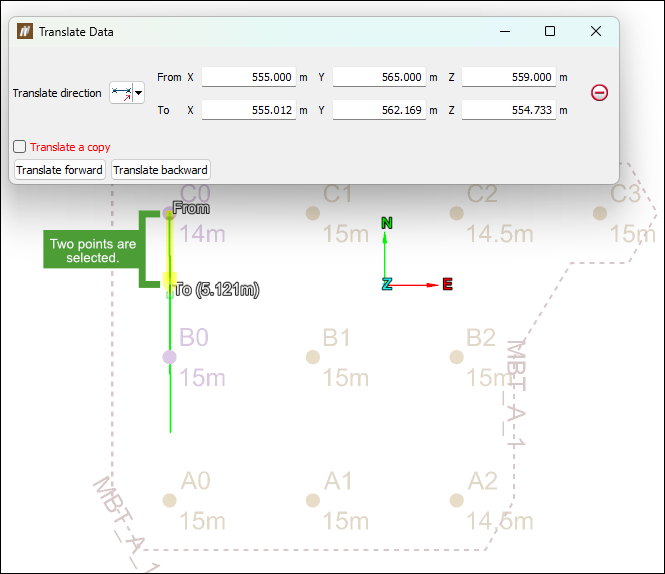
-
Click Translate forward to perform the translation process. Use Transform backward to retrace the path back to the start position.
In the example below, Translate forward was selected.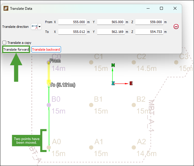
Note: Right-clicking on the input fields will display a context menu with additional basic options.![]()
 Rotate
Data can be rotated around the three axes (X, Y, Z) or around a user-defined axis.
To use the ![]() Rotate tool, follow these steps:
Rotate tool, follow these steps:
-
On the Geometry ribbon, go to the Transform group and select
Rotate.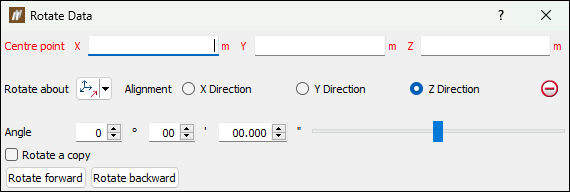
-
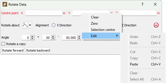
Select a Centre point of rotation. The centre of rotation can be selected in the view window or by entering coordinates in the panel.
Note: Right-clicking on Centre point fields will display a context menu with additional basic options.
-
Select the method of defining the rotation axis from the Rotate about drop-down list.
The panel will change to request additional inputs according to the selected Rotate about type. The Rotate about options are:
Two pointsRotate around an axis defined by two points. FacetRotate around an axis perpendicular to a facet. Axis alignedRotate about X, Y, or Z. Bearing and inclination
Rotate about an axis defined by a bearing and inclination angles. Action plane axis
Rotate about the action plane of active view.
- Select the object to be rotated in the project explorer and make sure that no other objects are highlighted.
- Enter a rotation Angle and use the Rotate forward and Rotate backward buttons to rotate clockwise and anti-clockwise.
In the example below, a point has been selected on the Line object from the cadcontainer to be rotated anti-clockwise by 90 degrees in Z Direction.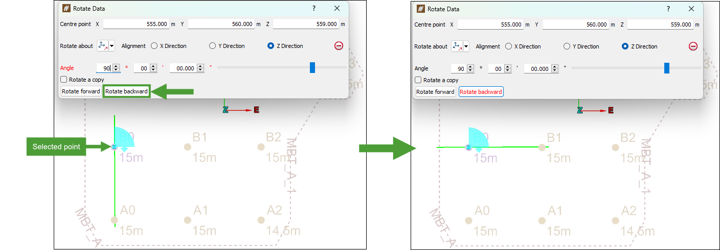
- Optionally, select Rotate a copy checkbox to rotate a duplicate of the original object each time Rotate forward or Rotate backward is selected.
Note: With Rotate a copy selected, select the new copy of the object to create another copy rotated further around the axis.
 Scale
Scale
The scaling tool allows data to be scaled in axial directions.
To use the ![]() Scale tool, follow these steps:
Scale tool, follow these steps:
-
On the Geometry ribbon, go to the Transform group and select
Scale.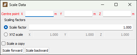
-
Select a Centre point about which the object is scaled.
Note: Right-clicking on Centre point field will display a context menu with additional basic options.
-
Enter a Scale factor to scale the object equally in all directions.
Or
Select XYZ scale and enter factors for each of the X, Y and Z directions to scale the object disproportionately.
Note: To scale scans horizontally, enter the scaling factor for X and Y, and set Z =
1.0. -
Optionally, select Scale a copy checkbox to duplicate the original object and scale the new copy each time Scale forward or Scale backward is selected.
-
Select the object to be scaled in the project explorer and make sure that no other objects are highlighted.
-
Click Scale forward to increase the object size by the scale factor, or click Scale backward to decrease the object size. In the example below, a point within a Polygon object was selected to scale the polygon with Scale factor
2.000.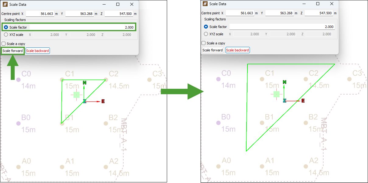
 Mirror
The ![]() Mirror tool allows you to create a mirror image of, or reverse the original data.
Mirror tool allows you to create a mirror image of, or reverse the original data.
To use it, follow these steps:
-
On the Geometry ribbon, go to the Transform group and select
Mirror.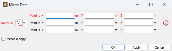
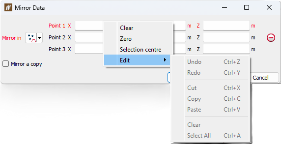
Note: Right-clicking on the input fields will display a context menu with additional basic options.
-
Select the method of defining the mirror plane from the Mirror in drop-down list. The panel will change to request additional inputs according to the selected Mirror in type.
The mirror plane options are: Three points
Define the plane by specifying three points.  Point and normal
Define the plane by specifying one point and defining its normal direction.  Point and orientation
Define the plane by specifying one point and orienting the plane so the current view is its normal.  Facet and offset
Pick a triangle to define the plane's orientation, and then specify how far above or below that facet the plane should be.  Point, strike and dip
Define the plane by specifying a point and then providing dip or strike angles to specify the orientation of the plane through that point.  Axis aligned
Define the plane by selecting an axis pair then picking a point to define the offset along the third axis.  Action plane
Use the action plane of the current view. -
Optionally, select the Mirror a copy checkbox to create a copy of the original data reversed in the mirror plane. To reverse the original data in the plane of the mirror, clear the Mirror a copy checkbox.
-
Select the object to be mirrored in the project explorer and make sure that no other objects are highlighted.
-
Click OK or Apply.
Note: If you clicked Apply, close the tool with the Cancel button. If you click OK, the function will run again, undoing the mirroring.
