Flowchart
The Flowchart tab is used for adding process flow equipment to a setup and designing the flow of material.
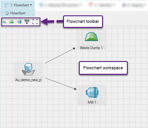
A number of components can be added and are described in the table below. They are separated into two distinct types of components - virtual and imported. Virtual components are added from the Flowchart toolbar and have no associated geometry. Imported components are stored in the Project Explorer and added to the setup via drag and drop functionality.
| Icon | Label | Type | Description |
|
|
Virtual waste dump | Virtual | A waste dump is used to store waste material sent from a pit. |
|
|
Mill | Virtual | A mill processes material sent from a pit. |
|
|
Pit (block) | Imported | A mining site is called a pit. The pit needs to be a block model to be added to an Origin Blocks setup. |
|
|
Waste dump (block) | Imported | A waste utility is used to store waste material sent from a pit. It contains geometrical which is useful when you want to pinpoint exactly where you are sending waste material to. For the imported waste dump to be successfully added to the setup, it needs to be a block model. |
|
|
Virtual stockpile | Virtual | A reserve stockpile is a temporary storage site for low grade material. Later on in the schedule, material is sent from a stockpile to the mill to achieve end of period targets. |
Once components have been added, the flow of material can be defined by linking them together. To create a link between component A and B, complete the following steps:
-
Click on component A. A white circle with a black outline will appear in the middle of the component.
-
Click on the circle in the middle of component A an drag the arrow all the way to the black circle on component B and wait until the circle has a grey outline.
-
Release the mouse. The link should be created.
