Updating a Waste Dump
Once a new waste dump has been created or an Imported Utility is added, the areas of the dumps can be coded or reset. Waste dump areas are used in Maptek Evolution to enable the segregation of different waste areas within a single waste dump. This can be useful for material encapsulation, ensuring certain material types are dumped into their respective areas or simply controlling waste dump release strategies.
There are two methods to code blocks in a waste dump:
-
Coding using DXF — Using a polygon DXF from another General Mine Planning (GMP) Software Package.
-
Manual coding — Manually selecting individual blocks and rename the area code in the Properties window.
Coding Using DXF
Several guidelines should be followed to ensure the DXF data used for coding the blocks is effective and efficient:
-
Only polygon data can be used to code blocks in Maptek Evolution
-
The polygon strings must be closed. Only the blocks within the polygon will be coded with the new value.
The elevation of the polygons must be within the block height of the blocks to be coded. It is best to create the polygons on the block model centroid elevations to ensure accurate coding. A polygon is required for each elevation requiring the new code, similar to contouring.
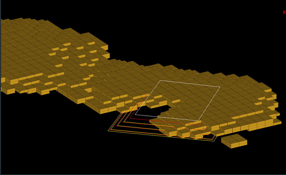
After the required polygon file has been created in General Mine Planning Software and converted to a DXF, import it into Maptek Evolution to visually check the file.
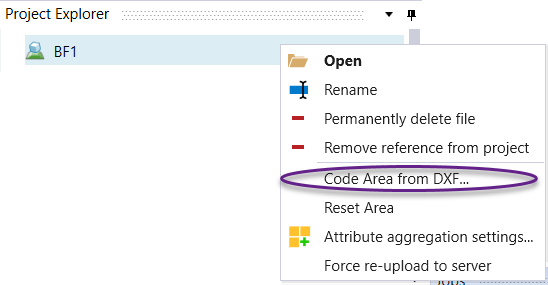
After a visual confirmation has been performed, right click on the waste utility that requires coding in the project explorer and select the Code Area from DXF option.
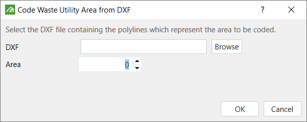
Select Browse to locate the required DXF to code the new area.
Locate and select the DXF and click on Open.
Once the DXF has been selected, enter the Area number for the new section to be coded with the DXF, (different to default Area).
Press OK and Evolution will perform the block coding operation. If there are a lot of blocks to be coded, it is best to close the Utility viewer to increase the speed of the coding (this reduces the need to re-render the model in the viewer as it performs the operation).
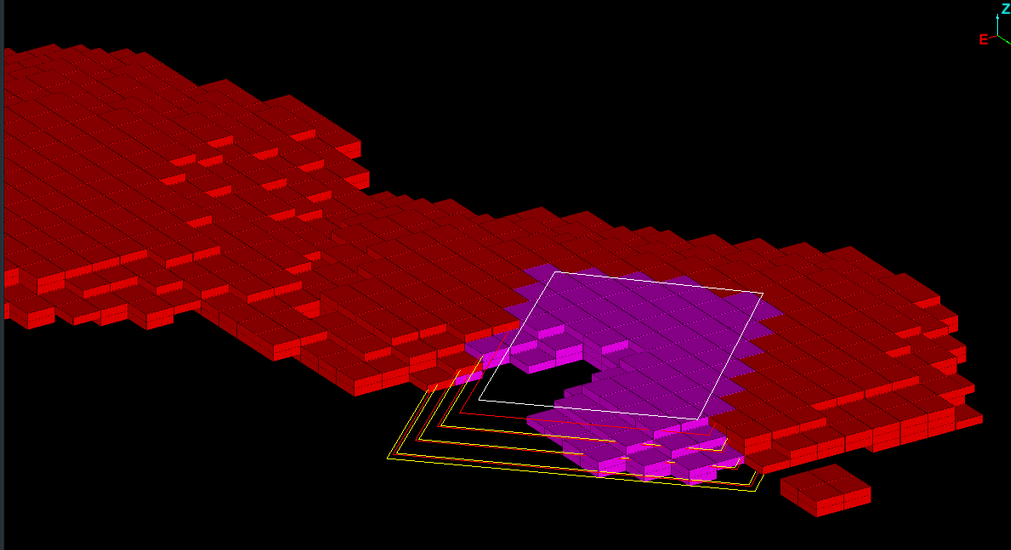
Once the coding is complete, either re-open the utility in the viewer or if already open, open the Colours tab in the Properties window. Select the Dynamic Colour option and choose Area under the drop down to colour the model by Area. It can be seen that the blocks inside the DXF polygons are now coded with a different Area number (and colour).
Manual Coding
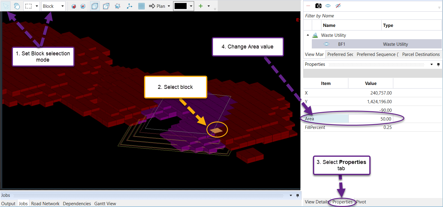
To code individual blocks or edit individual blocks, simply double click on the required block. In the Options window, open the Properties tab.
To edit the Area number, simply double click on the number in the Area field and enter the new number. Press Enter to register the change.
Press Save ![]() under Project in the Ribbon control menu. If it is grayed out, it is a suggestion that Evolution has not recognised a change in the project.
under Project in the Ribbon control menu. If it is grayed out, it is a suggestion that Evolution has not recognised a change in the project.
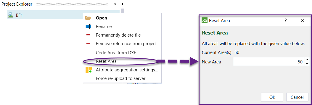
To reset the default area for the utility, simply select the Reset Area option and enter in the new area value. All of the areas previously coded or numbered will be set to this new default code.