Dependencies
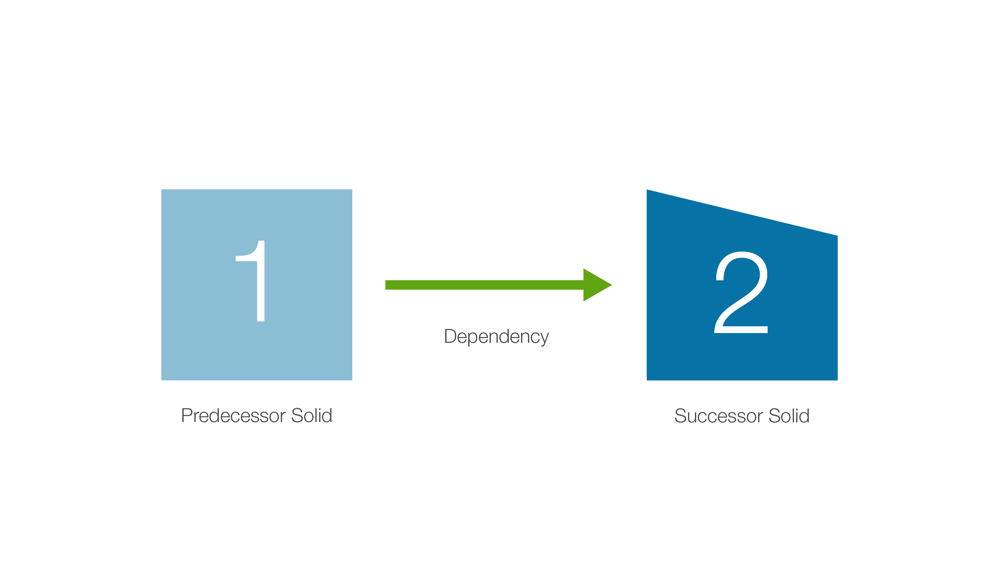
A dependency is a relationship between two solids, solid 1 and solid 2, where the relationship dictates that solid 1 is mined before solid 2. Solid 1 is known as the predecessor solid while solid 2 is called the successor solid as described in the diagram below.
Where do I Create a Dependency Set
The Dependencies tab is part of the Report Window and is used in conjunction with the viewer to create dependency sets.
How to Create a Dependency Set
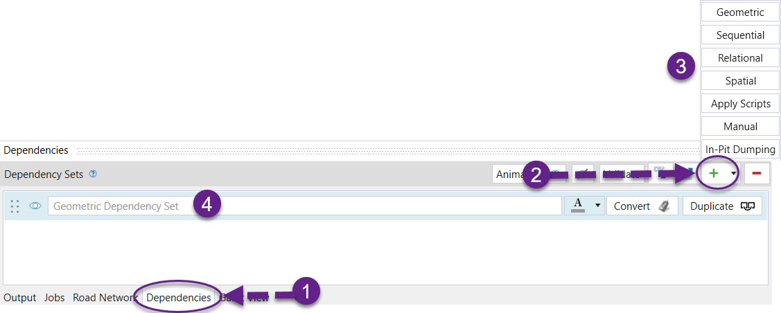
To create a dependency set:
-
Open the Dependencies tab from the Reporting Window tabs and the viewer tab simultaneously.
-
Click
 and choose a type of dependency set from the dropdown menu.
 -
A new panel will appear. Provide the information required (see information below) and click OK.
-
When a dependency set type is chosen, it will be added to the list displayed in the Dependencies window.
-
Once the dependencies have been created, save the changes so that they are stored in the model. The dependencies are displayed in the viewer as well as the Properties > Cell Dependencies tab.
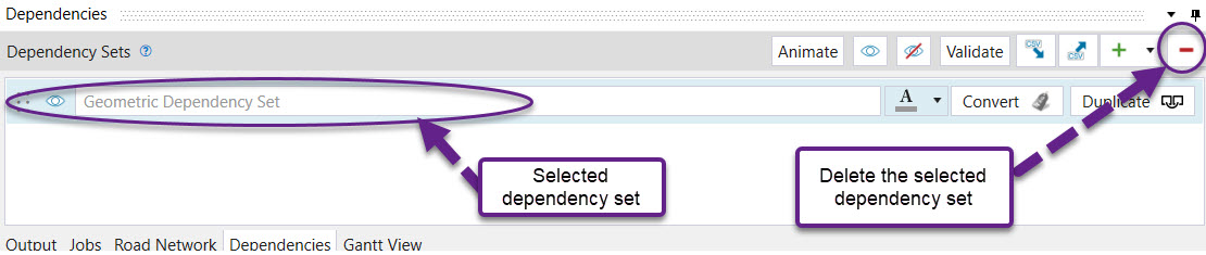
How to Delete a Dependency Set
To delete a dependency set, select the dependency set in the Dependencies window and then click ![]() , as shown below.
, as shown below.
Types of Dependency Sets
Dependency sets allow you to place solids in a known mining order which must be honoured during server side processing. Evolution offers multiple ways of ordering solids. The following is a table of types of dependency sets that can be created:
| Dependency type | Description |
| Geometric | Based on the geometry and relative location of solids. |
| Sequential | Based on the order of solids when put in array according to the selected variable. |
| Relational | Based on user-defined relationships which can be restricted to specific regions in a model using filters. |
| Spatial | Based on the relative spatial attributes of a solid. |
| Manual (solid) | Based entirely on user selection. |
| In-pit dumping | Used to create a direct relationship between a waste solid from a mining site and the location in a waste utility it is being sent to. |
Geometric dependency sets
Dependencies can be created between solids based on their shape, size and relative location. It is recommended that geometric dependencies be added to every model to make the final mining sequence generated more realistic.
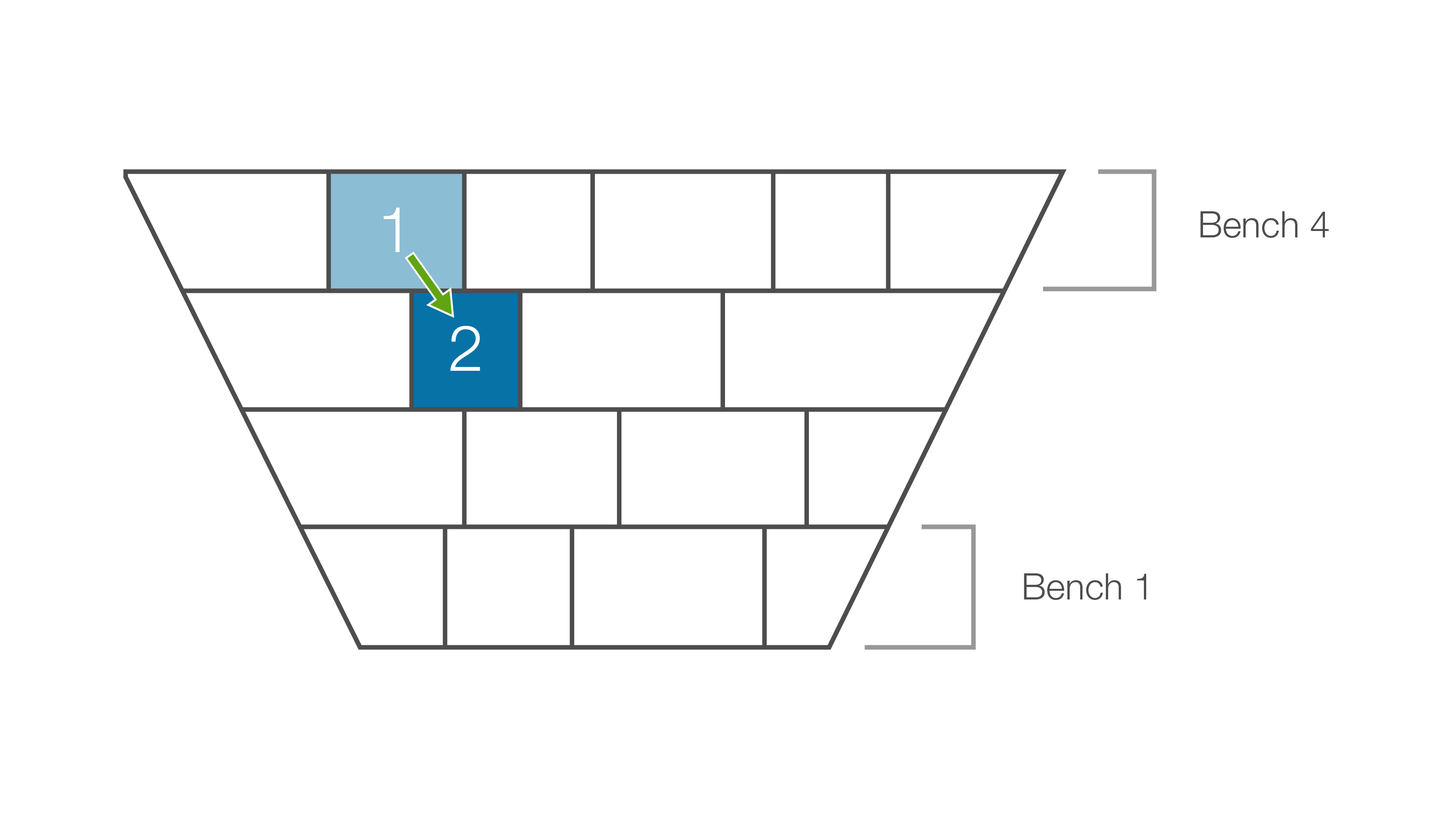
The above image is an example of a geometric dependency. Solid 1 needs to be mined before solid 2 because of its relative location.
To create geometric dependencies:
-
Open the Dependencies tab in the Reporting Window.
-
Click the
 in the Dependency Sets ribbon and select Geometric from the drop down menu. The Generate Geometric Dependencies panel will appear.
 -
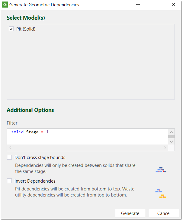
Select the model(s) you wish to apply the dependencies to.
-
Optionally, add a dependency filter in the Filter text area. This filter is inclusive so only the given solids are included in the dependency generation. You may use any geometric attribute available in your model as a filter with the following syntax:
solid.<attribute> = <value>
-
Select the checkboxes for any dependency options you wish to apply.
-
Click Generate.
The dependency can be found in your Dependencies viewer.

Sequential dependency sets
Sequential dependencies place solids in an order depending on a variable selected from the model. For sequential dependencies to be applicable, the value for each solid must be unique.
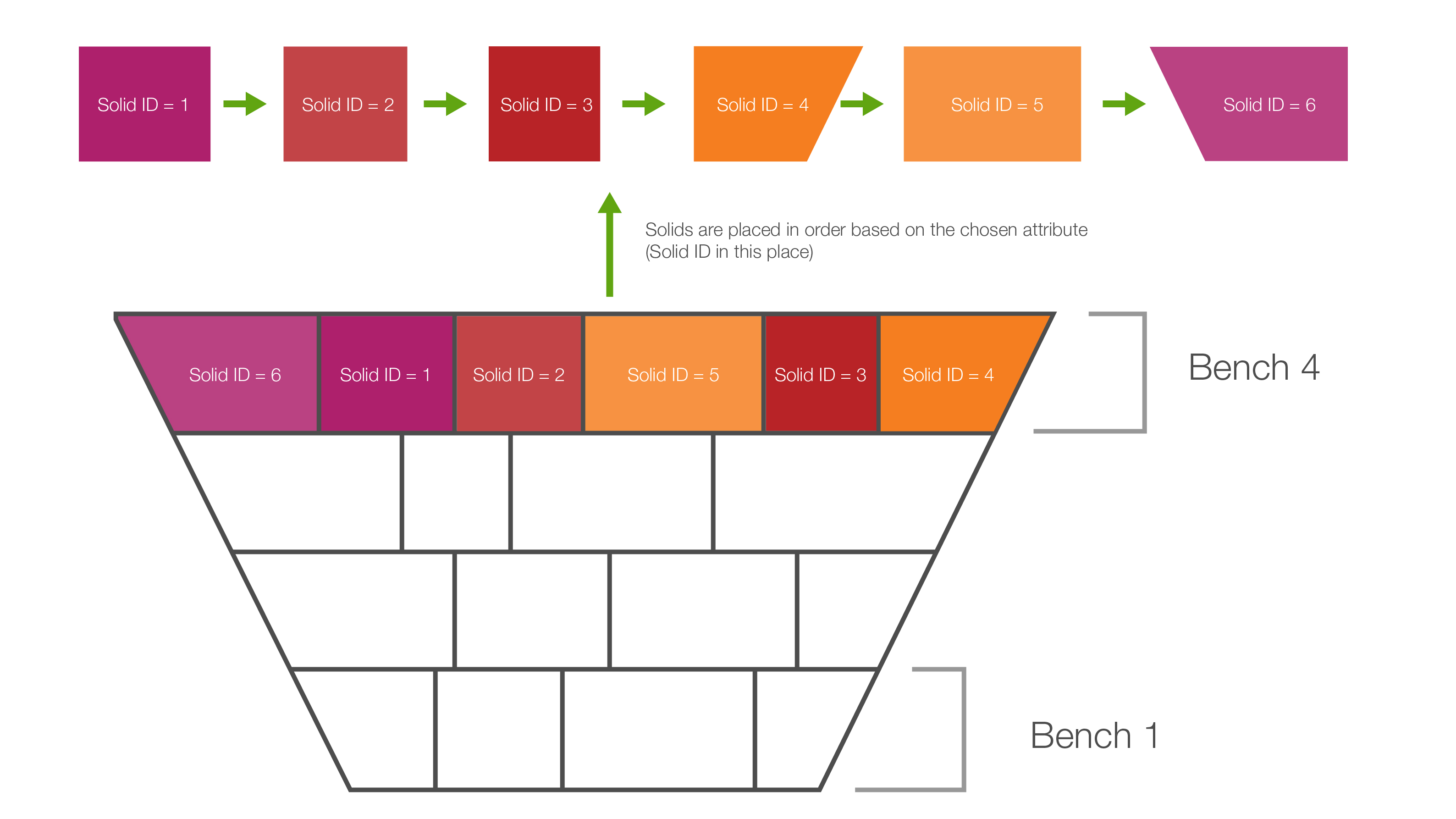
In the example above, the mass of each solid is set to a unique value. This is a highly unlikely scenario in the real world, however serves the purpose of demonstrating a sequential dependency.
Relational dependency sets
The Relational dependency set panel allows for more complex rules to be defined between predecessor and successor solids. There are four parts to a relational dependency rule:
- Predecessor column
The predecessor is the solid that has an outgoing link to a successor solid. Set the predecessor column to a attribute from the model dataset. - Successor column
The successor is the solid that has an incoming link from a predecessor solid. The successor column is always the same attribute used to set the predecessor column. - Type
The type of relationship between solid A and solid B can either be based on absolute value or indexed. - Offset
The offset is the difference between the predecessor column value in solid A and the successor column value in solid B. If the type selected is absolute, then the offset is the difference in the column variable value between solid A and solid B. If the type selected is indexed, the solids need to be first put in order from lowest to highest column attribute value. Each solid will have an index or a position. The offset will then be the difference between the positions of the predecessor and successor solids. - Operation
The relationship between the predecessor column value in solid A and the successor column value in solid B i.e. equal, less than, greater than or a combination.
On top of defining rules between two solids, filters can be added which restrict the application of a rule to regions of the model(s). Common attributes include area, stage, strip or bench.
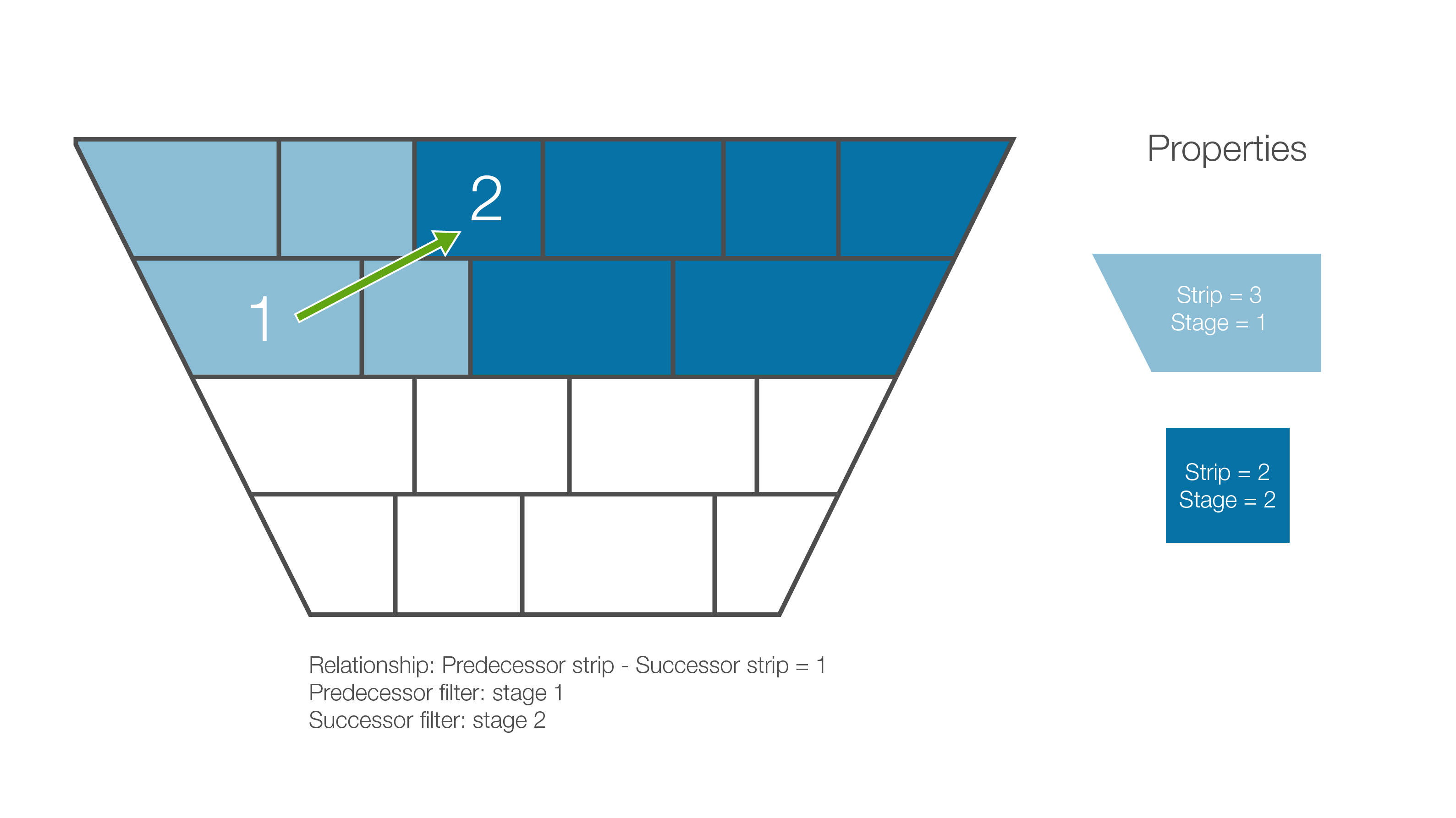
In the example above, we define the relationship between the predecessor and successor solid like this:

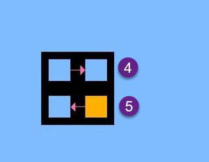
In the example above the we define the predecessor filter (1) and the successor filter (2) by using the following expressions:
(1) solid.Stage = 1
(2) solid.Stage = 2
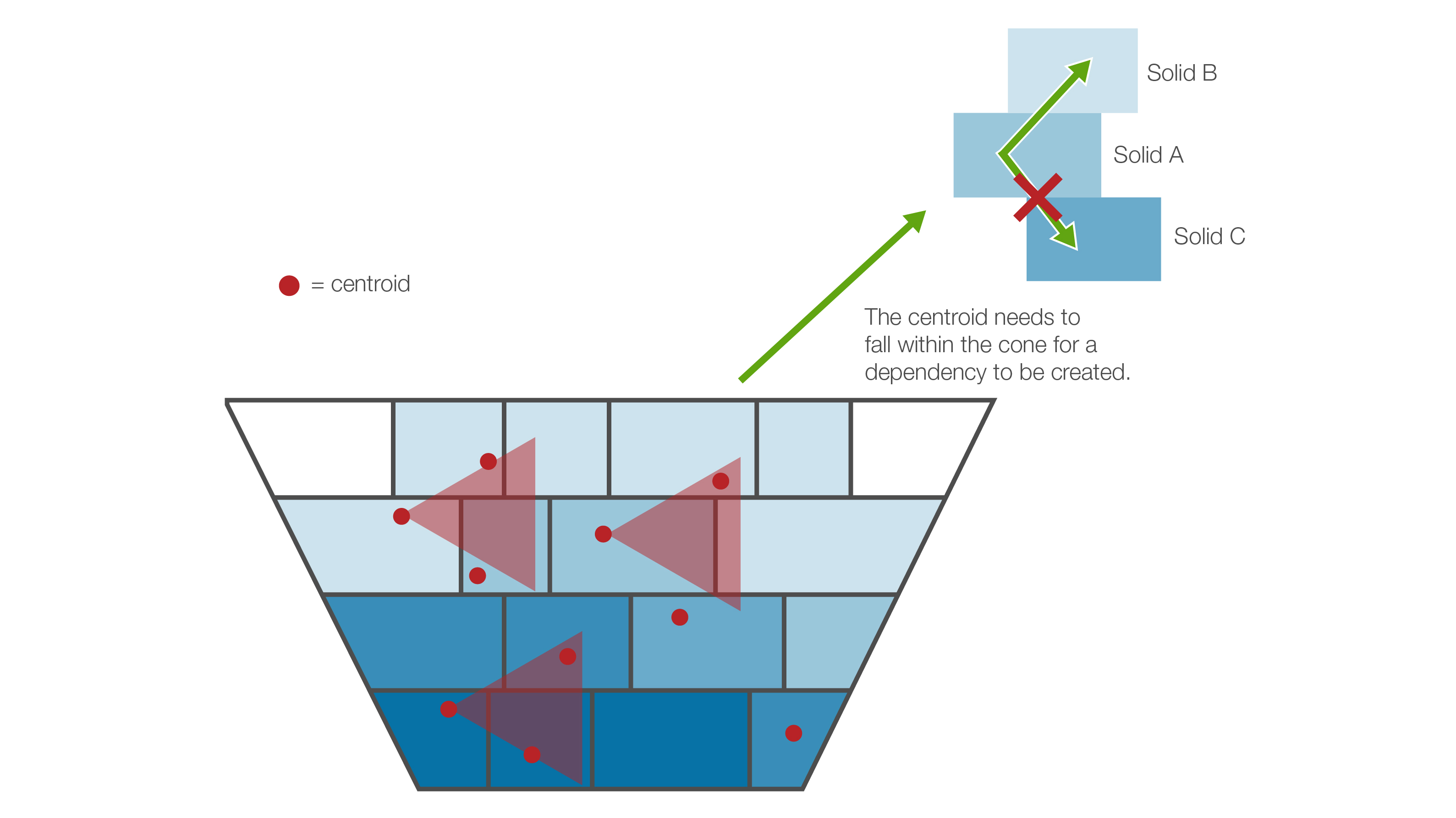
Spatial dependency sets
Spatial dependency sets have been added so that you can easily create dependencies between solids based on their spatial attributes. Once you have defined a spatial dependency, it will be repeated throughout the model based on the definition provided.
To create spatial dependencies:
-
Click
and select Spatial from the drop down menu (see How to Create a Dependency Set). -
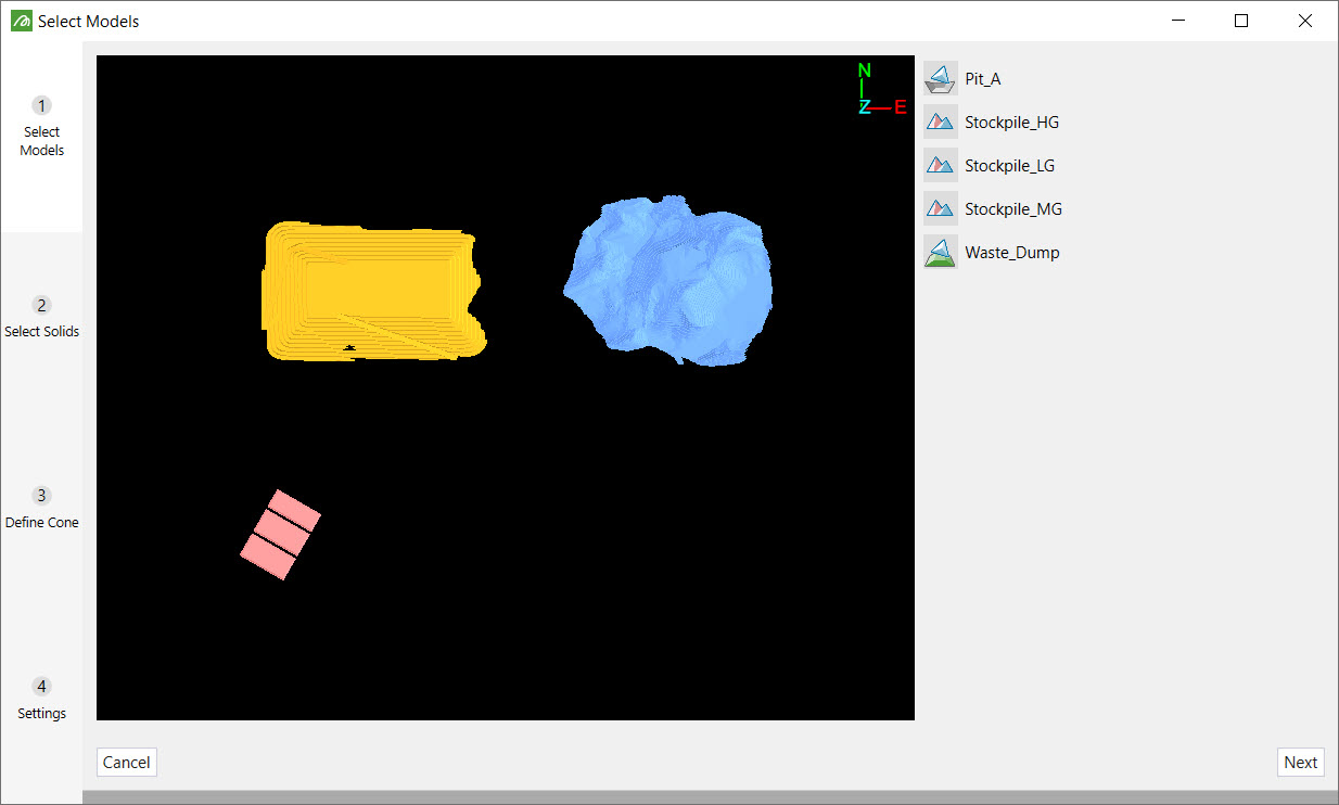
Select the models to create dependencies in.
-
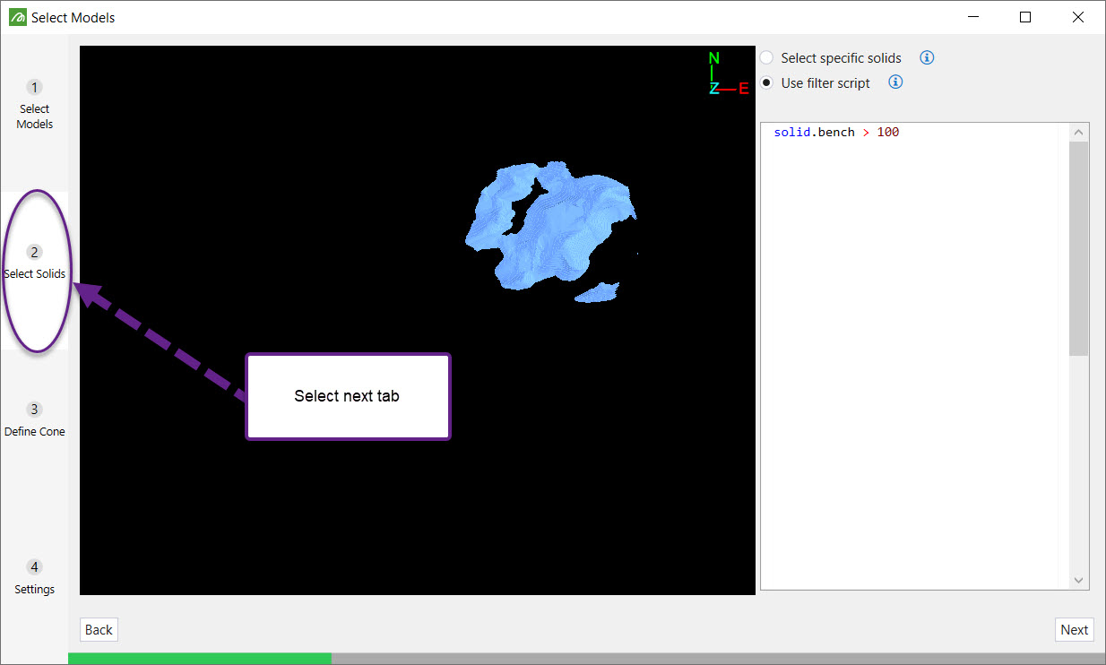
Go to the next tab Select Solids. Either manually select the solids to apply the dependencies or use a filter script i.e. solid.bench > 100.
-
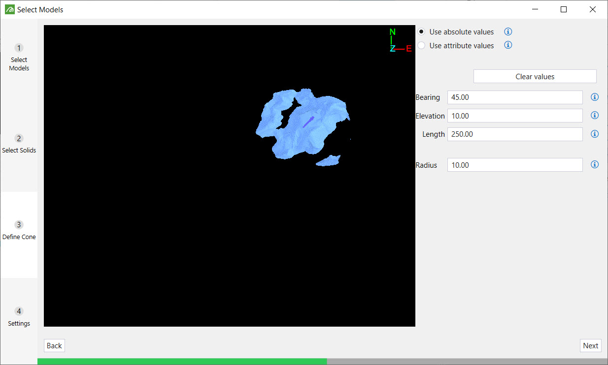
Go to the next tab Define Cone. Either manually define the bearing, elevation, length and radius by entering values or by clicking the model, or select attributes from the model.
-
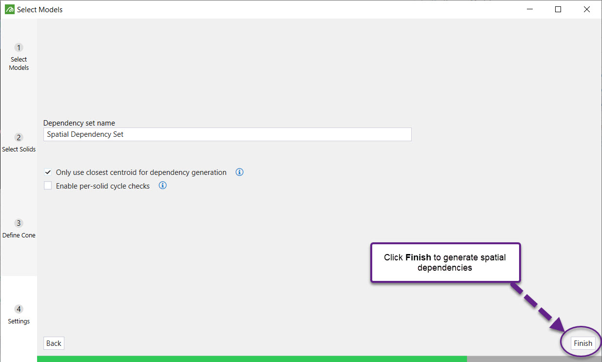
Go to the next tab Settings. Provide a name for the dependency set. There are also a couple of options you can choose to select when generating dependencies:
-
Only use closest centroid for dependency generation
By default, dependencies will be drawn between each solid and all solids whose centroid fall within the projected cone. This option limits the dependency generation to a maximum of one incoming dependency per solid. -
Enable per-solid cycle checks
By default, if any dependency drawn is determined cyclic, then no dependencies will be added to the model. This option allows dependencies that are non-cyclic to be drawn, but because each dependency needs to be checked, will take longer to generate.
-
-
Click Finish.
In-pit dumping dependency sets
In pit dumping functionality was added to the software to be able to simplify the creation of model to waste utility dependencies.
Waste dumping dependencies can be created by completing the following steps:
- Click and select In-pit dumping from the drop down menu (see How to Create a Dependency Set).
-
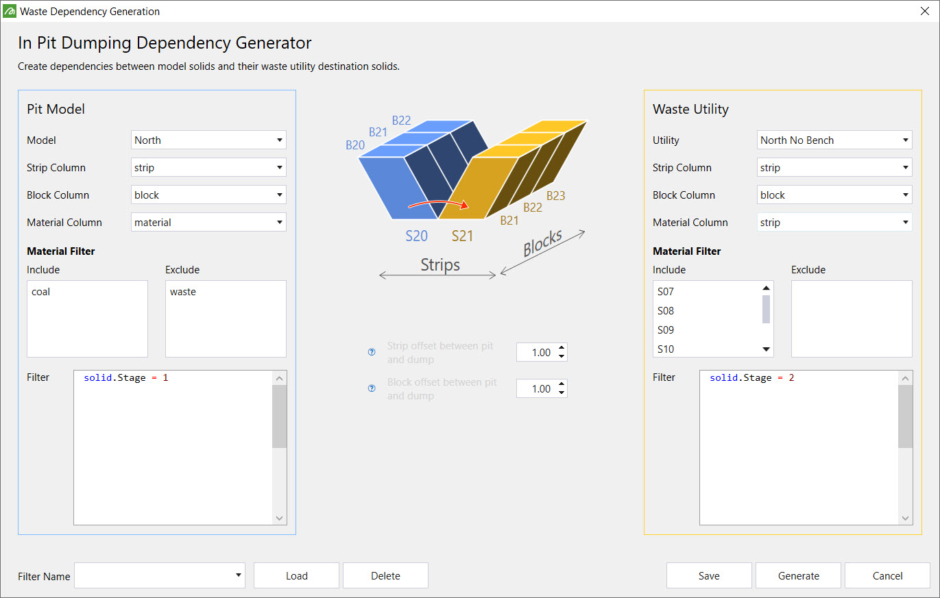
Provide values for the fields shown below and click the Generate button. In a typical scenario, you would select a block in both the model and the waste utility, and record block and strip column values. This is important for filling in the strip and block offsets which are simply the difference between the model and the waste utility column values.
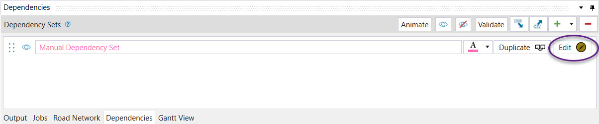
Manual (solid) dependency sets
Manually create dependencies from one solid to another by using the steps below.
- Go into Interactive mode.
- Click
 to add Manual dependencies from the drop-down menu.
 - Click Edit, next to the initialised manual dependency set in the Dependencies window.
-
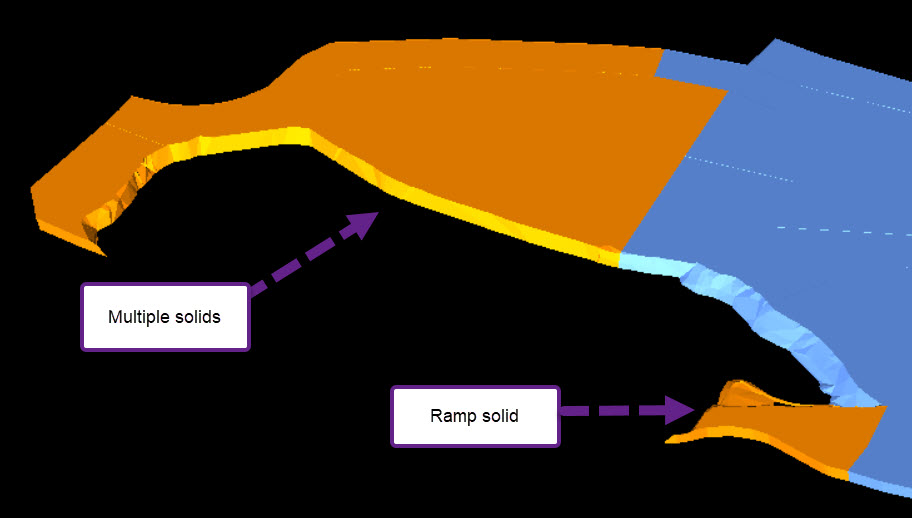
Select a solid to schedule then hold Key A on the keyboard and select another block to draw a dependency to. This will draw an arrow to that solid as shown below.
-
To create a dependency with a reversed arrow, repeat step 3 but this time hold Key D.

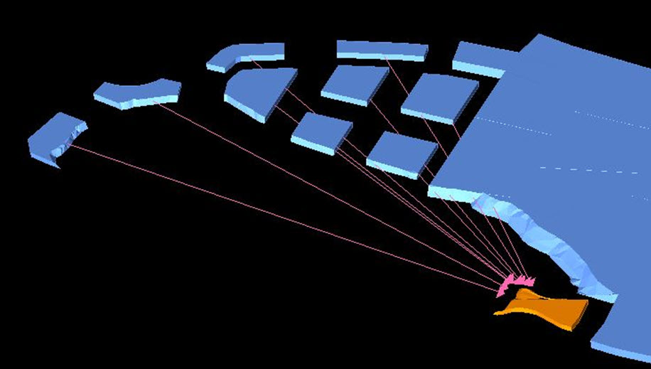
Create dependencies from multiple solids to a single solid using the steps below.
-
Hold down Shift and select solids to add dependency.
-
Hold Key A.
-
Select the ramp solid.