Dependencies
Source file: origin-reserve-setups-viewer-dependencies.htm
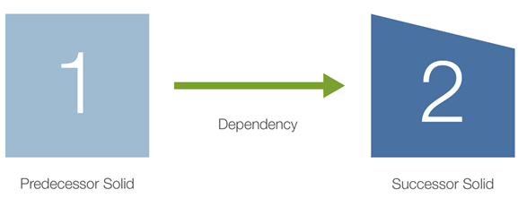
A dependency is a relationship between two solids. Dependency sets allow you to place solids in a known mining order that Evolution will honour while processing your setup. In the case there are two solids, Solid 1 and Solid 2, the dependency between them will dictate mining Solid 1 (called the Predecessor Solid) before Solid 2 (the Successor Solid), as shown in the diagram below.
Creating dependencies
To create a dependency set, go to the ![]() Viewer and select the Dependencies tab at the bottom of the screen. Next, click
Viewer and select the Dependencies tab at the bottom of the screen. Next, click ![]() (Add New Dependencies) in the toolbar and select the dependency type you wish to create.
(Add New Dependencies) in the toolbar and select the dependency type you wish to create.
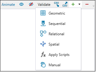
The table below lists the dependency types listed in Solids:
| Dependency type | Description |
|---|---|
| Geometric | Use the geometry and relative location of solids to create logical dependencies. |
| Sequential | Based on the ordered values of solid attributes. |
| Relational |
Based on relationships between the values of selected attributes. Note: In a dependency set with filters, the relationships can be restricted to specific regions within the model. |
| Spatial | Based on the direction that you define. |
| Apply Scripts | Based on the previously saved dependency set scripts. |
| Manual | Based on the solids you select in the viewer. |
The next steps that you will have to complete to create a dependency set will depend on the dependency type you select.
Tip: See Managing dependencies for more information on each toolbar button.
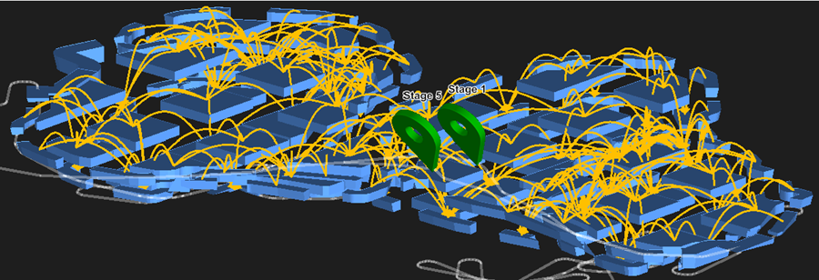
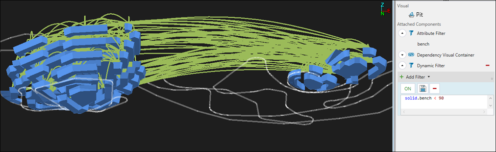
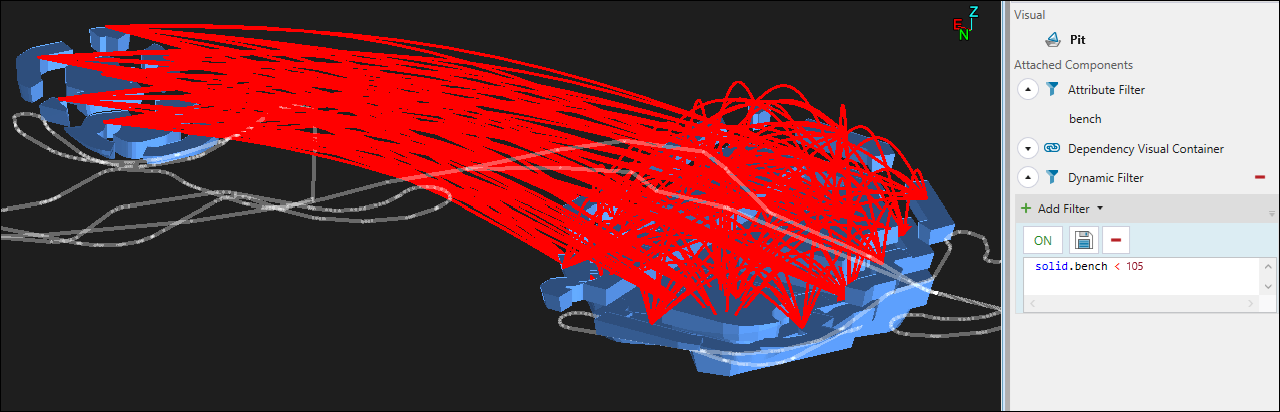
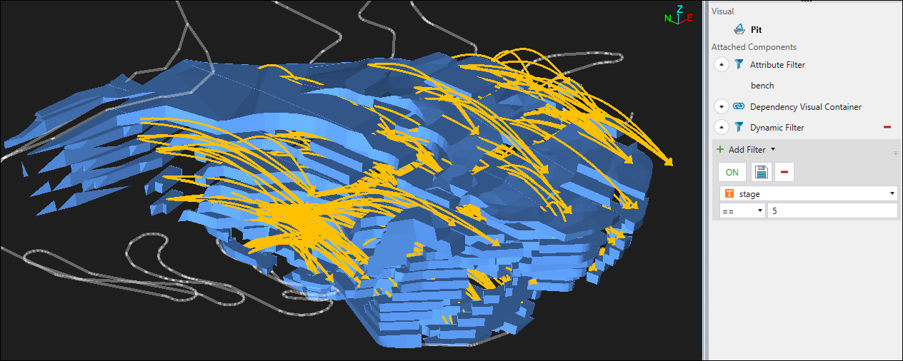
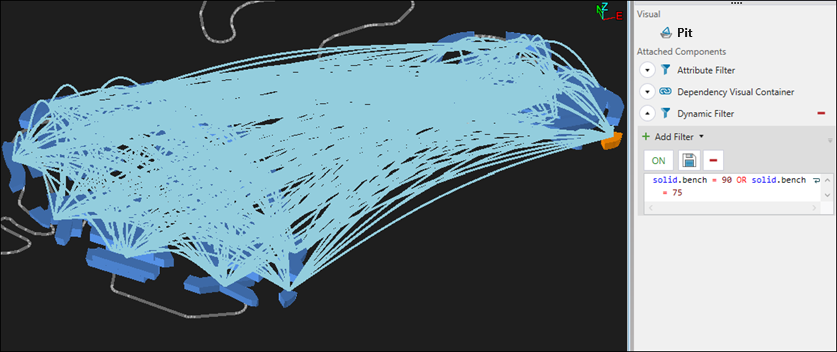
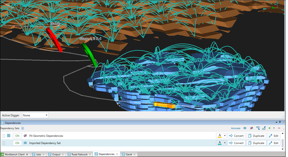
Tip: Use the Dynamic Filter to improve the visibility of the dependencies you have created within your model. In the example below, the model was filtered to display only the benches included in the Geometric dependency set.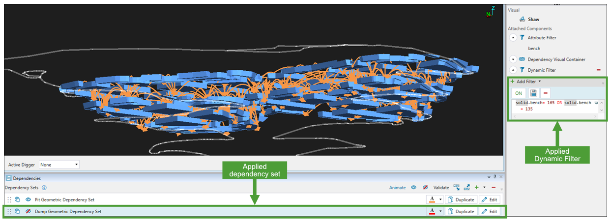
See Dynamic Filter for more information.
Geometric dependency sets
You can create dependencies between solids based on their shape, size, and relative location within the model.
Tip: To achieve a realistic mining sequence, add geometric dependencies to each model in your setup.
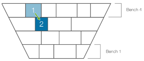
The image below is an example of a geometric dependency where Solid 1 must be mined before Solid 2 due to their relative location.
Follow these steps to create a geometric dependency set:
-
Click the
 (Add New Dependencies) button in the Dependencies tab and select Geometric (see Creating dependencies for more information).
 -
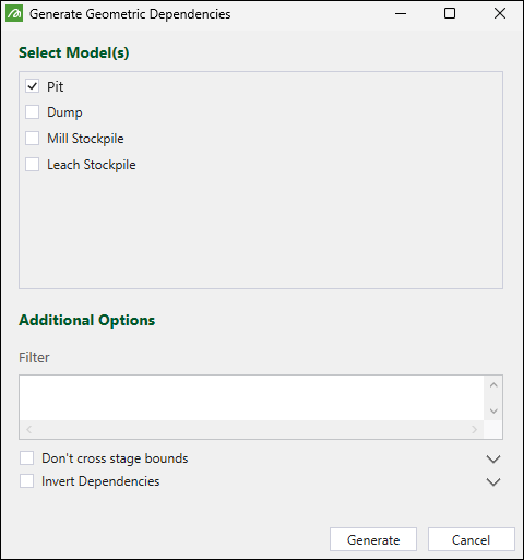
In the Generate Geometric Dependencies panel, select the models you wish to apply the dependencies to.
-
Optionally, configure the following:
-
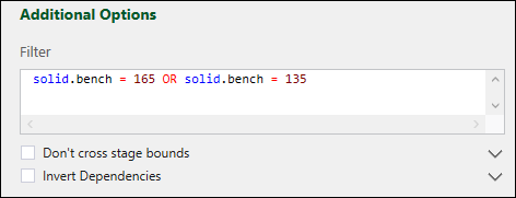
Add a dependency filter in the Filter field. Only the solids specified by the filter will be included in the generated dependencies. You can use any geometric attribute available in your model.
-
Select the Don’t cross stage bounds checkbox to create dependencies only between solids that share the same stage.
-
Select the Invert Dependencies checkbox to create pit dependencies from bottom to top, and waste utility dependencies from top to bottom.
-
-
Click Generate to confirm your settings. Evolution will inform you about the number of the created dependencies by displaying a pop-up at the bottom of your screen. The created dependencies will be shown in the viewer.
See Managing dependencies for information on customising, sharing, and animating dependency sets.
Sequential dependency sets
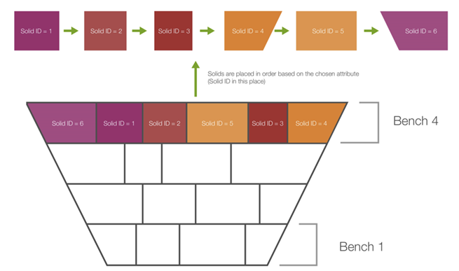
Sequential dependencies place solids in an order according to a variable that you select from the model. For sequential dependencies to be applicable, the value for each solid must be unique.
Follow these steps to create a sequential dependency set:
-
Click the
(Add New Dependencies) button in the Dependencies tab and select Sequential (see Creating dependencies for more information). -
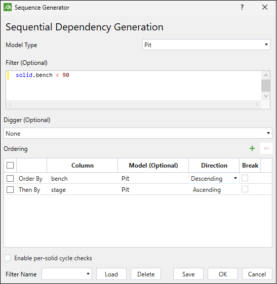
In the Sequence Generator panel, configure the following:
-
From the Model Type drop-down, select the model to generate the dependency set for.
-
Optionally, apply a filter in the Filter field. Only the solids specified by the filter will be included in the generated dependencies.
-
Optionally, specify the digger to which the dependency applies.
-
Click
 to add a row to the Ordering table. Define the order of your sequence by selecting the attributes from the drop-down in each column:
-
Column. Specify the attribute according to which Evolution should generate the sequence.
-
Model (Optional). Select the model to which the sequence should apply.
-
Direction. Select the direction in which the attribute selected in the Column should be ordered:
-
Ascending
Example
If you select bench as the sequence attribute, the bench numbers will be ordered in the ascending order: 100, 200, 300, 400. -
Descending
Example
If you select bench as the sequence attribute, the bench numbers will be ordered in the descending order: 400, 300, 200, 100.
-
-
Break. If you select this checkbox, Evolution will not create the dependency if it finds a solid with the same value.
-
-
Optionally, select the Enable per-solid cycle checks checkbox. By default, Evolution will not add any dependencies if any of them could cause a cycle. However, if you select this option, Evolution will add all dependencies that do not cause a cycle.
Note: Selecting this option will result in longer dependency creation times.
-
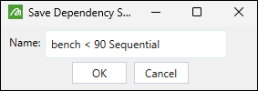
Optionally, you can save the sequential dependency filter that you have applied by clicking Save at the bottom of the Sequence Generator panel. Evolution will display the Save Dependency Settings panel for you to enter the name of the filter to be saved.
All previously saved sequential dependency sets will be listed in the drop-down at the bottom of the Sequence Generator panel. Select the required set from the list and click Load to populate the panel with the required settings.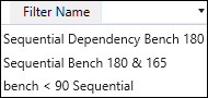
-
-
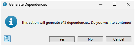
Click OK. Evolution will display the Generate Dependencies dialog box informing you about the number of dependencies to be created. Click Yes to proceed with dependency generation.
See Managing dependencies for information on customising, sharing, and animating dependency sets.
Relational dependency sets
Relational dependencies allow you to define more complex rules between the predecessor and successor solids.
Follow these steps to create a relational dependency set:
-
Click the
(Add New Dependencies) button in the Dependencies tab and select Relational (see Creating dependencies for more information).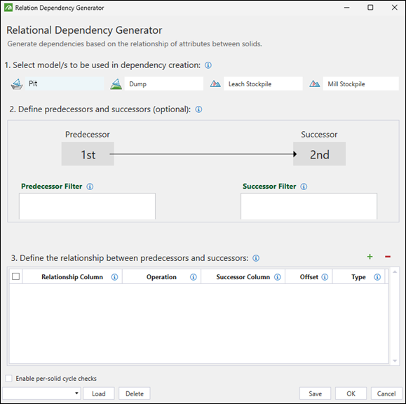
-
In the Relation Dependency Generator panel, configure the following:
-
Select the models for which dependencies should be created.
Note: If you select multiple models, Evolution will also generate dependencies between them.
-
Optionally, use filter scripts to define the predecessor and successor solids.
-
Define the relationship between predecessors and successors. To do so, click
 to add a relationship to the table. Next, configure each column according to the following information:
-
Relationship Column: The column that will be compared between the predecessor and successor. Select the appropriate attribute from the drop-down menu.
-
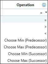
Operation: Indicates the difference between the predecessor and successor solids.
Note: The Min and Max options specify that only solids with the smallest or highest values for the given column will be considered as potential predecessors and successors.
-
Successor: The solid that has an incoming link from a predecessor solid. The Successor Column has always the same attribute as the one used to set the Relationship Column.
-
Offset: The difference between the Relationship Column value for Solid A and the Successor Column value for Solid B.
-
If you set the Type as Absolute, then the offset is the difference in the column variable value between the Solid A and Solid B. If you set the Type as Indexed, the solids will have to be first put in order from lowest to highest column attribute value. Each solid will have an index or a position. The offset will then be the difference between the positions of the predecessor and successor solids.
-
Type: Set this field to one of the following:
-
Absolute to compare the values according to their actual numeric or text value.
Or
-
Indexed to compare the values according to their relative order or rank.
-
-
-
Optionally, select the Enable per-solid cycle checks checkbox. By default, Evolution will not add any dependencies if any of them could cause a cycle. However, if you select this option, Evolution will add all dependencies that do not cause a cycle.
Note: Selecting this option will result in longer dependency creation times.
-
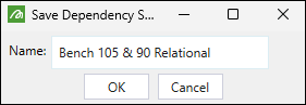
Optionally, you can save the relational dependency set that you have created by clicking Save at the bottom of the Relational Dependency Generator panel. Evolution will display the Save Dependency Settings panel for you to enter the name of the dependency.
All previously saved relational dependency sets will be listed in the drop-down at the bottom of the Relational Dependency Generator panel. Select the required set from the list and click Load to populate the panel with the required settings.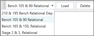
-
-
Click OK. Evolution will display the Generate Dependencies dialog box informing you about the number of dependencies to be created. Click Yes to proceed with dependency generation.
The created dependencies will be shown in the viewer.
 See Managing dependencies for information on customising, sharing, and animating dependency sets.
Spatial dependency sets
Spatial dependency sets allow you to easily create dependencies between solids based on spatial attributes. Once you have defined a spatial dependency, it will be repeated throughout the model according to the provided definition.
Important: For a dependency to be created, the centroid must fall within the cone, as shown in the image below.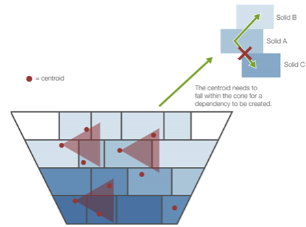
Follow these steps to create spatial dependencies:
-
Click the
(Add New Dependencies) button in the Dependencies tab and select Spatial (see Creating dependencies for more information). -
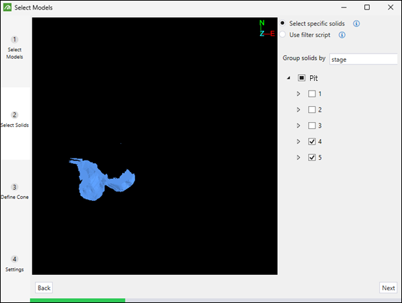
In the Select Models panel, configure the following:
-
Select models to create the dependencies for.
Tip: Select multiple models by Shift+click or Ctrl+click.
-
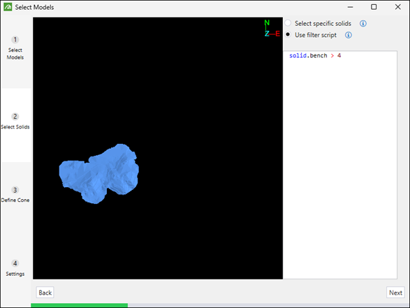
In the Select Solids tab, specify the solids to be included in the dependency set by selecting one of the following radio buttons:
-
Select specific solids: Group solids by each model and then by attribute (with default attribute being the selected bench column). Selecting or deselecting a group will apply to all solids within that group.
Or
-
Use filter script: Select the solids that pass the filter that you have defined.
Note: You must enter a script that evaluates to true or false.
-
-
-
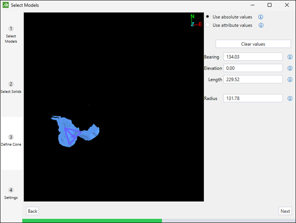
In the Define Cone tab, define the attributes of the cone by setting the following:
-
Choose which values to use by selecting one of the following radio buttons:
-
Use absolute values: A cone with the values that you define will be projected from the centroid of each solid. Evolution will create a dependency from Solid A to Solid B if the centroid of Solid B lies within the projected cone of Solid A.
Or
-
Use attribute values: For each solid, a cone with dimensions based on the values for the selected attributes will be projected from its centroid. Evolution will create a dependency from Solid A to Solid B if the centroid of Solid B lies within the projected cone of Solid A.
-
-
If you have selected the Use absolute values radio button, define the values manually by entering them in the following fields:
-
Bearing: The angle of the cone’s axis measured clockwise from north.
-
Elevation: The angle of the cone’s axis relative to the horizon. The value you specify must be between -90 and 90 degrees.
-
Length: The length of the cone’s axis.
-
Radius: The radius of the cone’s base.
Note: The units are the same as those used to define coordinates of the viewer solids.
Tip: You can also define the cone by drawing it in the viewer in the Select Models panel.
-
-
If you have selected the Use attribute values radio button, select the appropriate attribute from the Bearing, Elevation, Length, and Radius drop-downs.
-
-
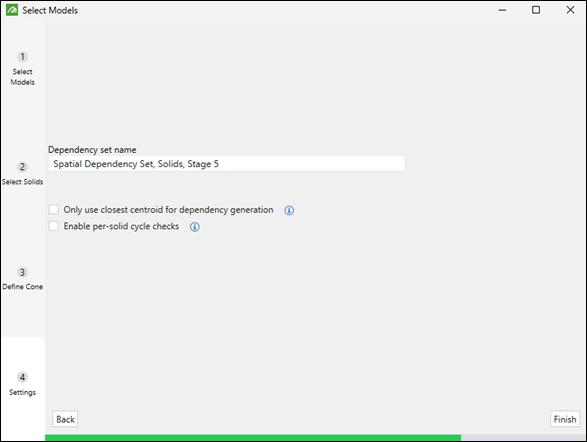
In the Settings tab, specify the following:
-
The name of the spatial dependency set.
-
Select the following radio buttons as required:
-
Only use the closest centroid for dependency generation
By default, Evolution creates dependencies from each solid to all solids with centroids that lie within the projected cone of that solid. If you select this option, Evolution will create maximally one outgoing dependency for each solid. The specified dependency target will be the solid whose centroid is closest to the source solid’s centroid and that lies within its projected cone.
-
Enable per-solid cycle checks
By default, Evolution will not add any dependencies if any of them could cause a cycle. However, if you select this option, Evolution will add all dependencies that do not cause a cycle.Note: Selecting this option will result in longer dependency creation times.
-
-
-
Click Finish. Evolution will display the Generate Dependencies dialog box informing you about the number of dependencies to be created. Click Yes to proceed with dependency generation.

Evolution will inform you about the number of the created dependencies by displaying a pop-up at the bottom of your screen.
See Managing dependencies for information on customising, sharing, and animating dependency sets.
Apply Scripts
To create dependency sets based on previously saved relational dependency scripts, follow these steps:
-
Click the
(Add New Dependencies) button in the Dependencies tab and select Apply Scripts (see Creating dependencies for more information). -
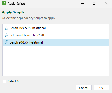
In the Apply Scripts panel, select the scripts you want to use and click Ok.
Tip: To apply multiple scripts, select them while pressing Ctrl or apply all listed scripts by clicking the Select All checkbox.
The script-based dependencies will be shown in the viewer.
See Managing dependencies for information on customising, sharing, and animating dependency sets.
Manual
You can manually create dependencies from one solid to another by completing the following steps:
-
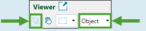
Click
 in the viewer toolbar to enter the interactive selection mode.
Note: Make sure you select Object from the drop-down in the toolbar.
-
Click the
(Add New Dependencies) button in the Dependencies tab and select Manual see Creating dependencies for more information). -
Evolution will add a Manual Dependency Set to the Dependencies tab at the bottom of your screen. Click
 Edit to configure it.
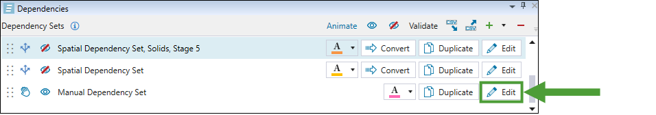
-
Create the required dependencies as follows:
-
Dependency between two solids: Select the preceding solid in the viewer, press A and select the succeeding solid to create a dependency between them. Evolution will link these two solids by drawing an arrow between them in the viewer, as shown below:
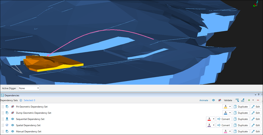
Alternatively, you can create a reversed dependency, where the first solid you select will be the successor. To do so, after selecting the successor solid, select the predecessor solid while pressing D. -
Dependency from multiple solids to a single (ramp) solid: Press Shift and select solids to create a dependency from. Next, press A and select the ramp solid. Evolution will link these solids by drawing an arrow from each predecessor solid to the specified successor solid in the viewer, as shown below:

See Managing dependencies for information on customising, sharing, and animating dependency sets.
-
Managing dependencies
All dependency sets that you have applied to your setup will be listed in the Dependencies tab at the bottom of the viewer.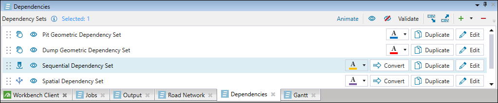
The tab toolbar features the following controls:
|
|
Enters the Animation mode that shows the progress of the depletion of the model based on the dependencies that you have set.
|
|
|
Show All Dependencies
Displays all dependency sets that were generated for the models in your setup. 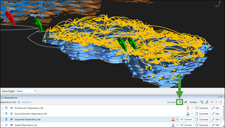 |
|
|
Hide All Dependencies
Hides all dependency sets that are displayed in the viewer. |
|
|
Import Dependencies
Allows you to import dependencies saved in a CSV file. After clicking 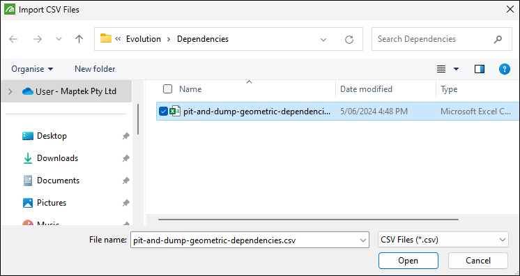 The imported dependencies will be displayed as a single dependency set. |
|
|
Export Visible Dependencies
Allows you to export the dependency that you currently have displayed in the viewer to the CSV file. After clicking 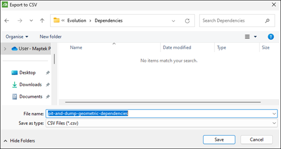 Note: All dependency sets exported together will be saved as one dependency set. See Import Dependencies for more information. |
|
|
Add New Dependencies
Allows you to add dependency sets to your setup. See Creating dependencies for more information. |
|
|
Delete Dependency Set Deletes the selected dependency set from the list. |

Tip: To rename a dependency set, double-click on it in the Dependency Sets list.
