Velocity
The following table describes the tools in the Velocity section of the Seismic tab.
| Tool | Description |
| Velocity Model Editor | Converts seismic data (and objects derived from seismic data, such as interpretations) from time to depth. |
| Depth Conversion | Applies a velocity model to seismic data, including data derived from seismic with a time attribute. Can also align seismic data to topography. |
Velocity Model Editor
Velocity models are used to convert seismic data (and data derived from seismic data, such as interpretations) from time to depth. This is useful for calculating the depth of seismic readings.
When seismic data are imported into Eureka, each seismic is associated with a default velocity model. The Velocity model editor can be used to refine the default model to incorporate more information, in particular, from drillhole-seismic ties.
Refining the model divides it into multiple intervals, defined by a set of surfaces.
Note: Related drillhole data must exist and a stratigraphy must be created for the associated drillholes before using the Velocity model editor.
-
Select Seismic > Velocity > Velocity model editor.
Velocity profile
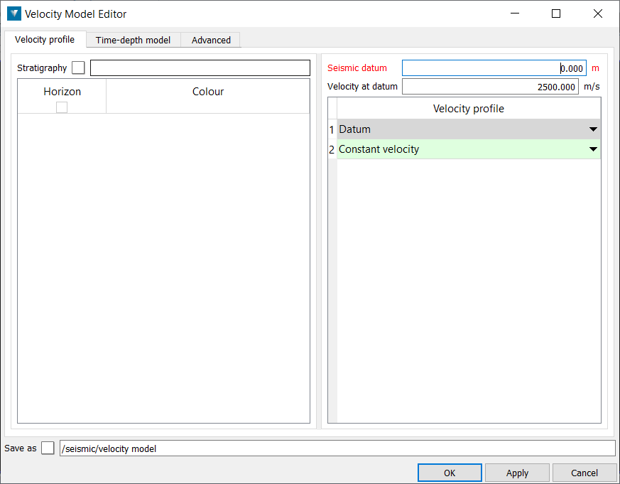
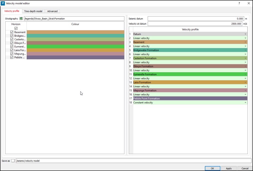
The Velocity profile tab is used to specify the horizons to be included in the velocity model, which velocity functions to use between each surface, and also the seismic datum information.
-
To edit the default velocity model or an existing velocity model, drag and drop it into the Save as field, or continue to create a new velocity model. The Stratigraphy table is used to specify which horizons to include in the velocity model.
-
Drag and drop the required stratigraphy into the Stratigraphy field.
-
Check the boxes next to the horizons that should be included in the model.
Note: To simplify interpretation of the seismic, building a velocity model initially from a single easily observed horizon and applying it, will adjust the seismic to be more in line with the drillholes. This velocity model can then be refined as more interpretations are made.
Seismic datum is the horizontal plane that corresponds to time zero in the seismic data. The datum is picked by the processing software that produced the SEG Y file, and is sometimes recorded in the SEG Y textual file header. Note that the top of the seismic data does not correspond with the ground.
Velocity at datum specifies the initial velocity at time zero from which velocities can be calculated. For velocity models that do not have surfaces defined, the velocity at datum is used to define the constant velocity for the whole model.
The Velocity profile table is used to specify which velocity function to apply to the intervals between each horizon:
-
Linear velocity calculates the velocity at any point in an interval from the velocities at the horizons immediately above and below the point. For points in the first interval, the velocity is calculated from the Velocity at datum and the velocity at the first horizon. For points below the lowest horizon, the velocity is calculated from the previous interval.
-
Constant velocity calculates the velocity at any point in an interval by assuming the velocity is equal to the average velocity over the whole interval. For points below the lowest horizon, the constant velocity is set to the last known average velocity; that is, the velocity at the lowest surface, or the velocity at the seismic datum if no horizons have been defined.
Time-depth model
The Time-depth model tab is used to specify the set of points with time-depth correspondences used to define each surface in the model.
-
Click the Add time-depth points from drillholes button to select the data to be used to refine the model.
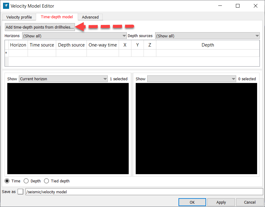
Add Time-Depth points from drillholes
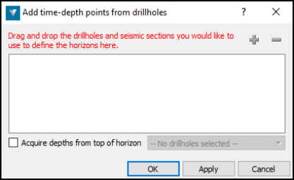
The Add time-depth points from drillholes panel is used to acquire a set of horizon points from a selection of drillholes. Drillholes are used to supply the depth information and seismic data are used to supply the time information.
Drag and drop the drillholes and the seismic data into the field, or use the + button to add all selected objects of these types. The - button can be used to remove selected objects from the field.
Tick the Acquire depths from top of horizon check-box to automatically acquire point depths from the specific horizon in each drillhole. If not checked, depths must be picked manually. Click OK. The Time-Depth model tab is redisplayed with a row for each drillhole that was dropped into the previous panel.
-
To show a single horizon at a time, select a horizon from the Define top of drop-down list. Horizons can be brought back using the tickboxes. To make time picks on one drillhole at a time, select a drillhole from the Depth sources drop-down list.
-
Click on the top row of the table. The corresponding drillhole is displayed in the right view and the seismic data closest to the drillhole is displayed in the left view.
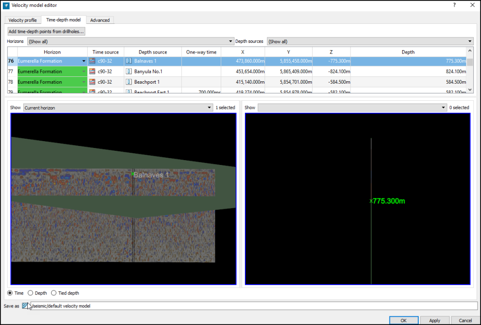
A slice of the seismic data is highlighted to indicate the part of the seismic data closest to the drillhole. The drillhole automatically zooms into the selected horizon.
-
Click on the required horizon on the seismic data in the left view. This fills the One-way time (s) column in the table above for that row. Any interpretations made on the seismic data can be added to the left view by dragging and dropping from the Explorer window.
-
Click in the next row and repeat the previous step for each row in the table. Note: All cells in the table are editable if required either by re-selecting the column and making a new pick, or by manually inputting a value.
As time picks are made, a surface appears in the left view indicating the horizon generated from current information. This may be hidden using the Show drop-down. When more than one horizon has been interpreted, it is possible to display all the surfaces in the view.
Note: Overlapping surfaces can cause erroneous results in velocity modelling. Using the show all option from the drop down menu can be used to validate the surfaces before applying the model.
As the model is built up, the left view can be switched between a time view of the seismic data and a depth view using the Time and Depth radio buttons. The two views can have their manipulation linked by selecting Tied depth.
If required, more data can now be selected from the Horizon and Depth sources drop-down menus and the process repeated.
Note: Additional drillholes and seismic can be added to the velocity model by reopening the Add time-depth points from drillholes window. All associated data should be added together, i.e. to associate a new drillhole with a previously used seismic section, the seismic section should be re-added with the drillhole.
6. Click OK. The velocity model is created/updated and applied to all seismic data associated with it. It is saved in the seismic container.
Note: Existing velocity models can be associated with seismic data using depth conversion.
Advanced
The Advanced tab contains extra settings not needed in most cases.
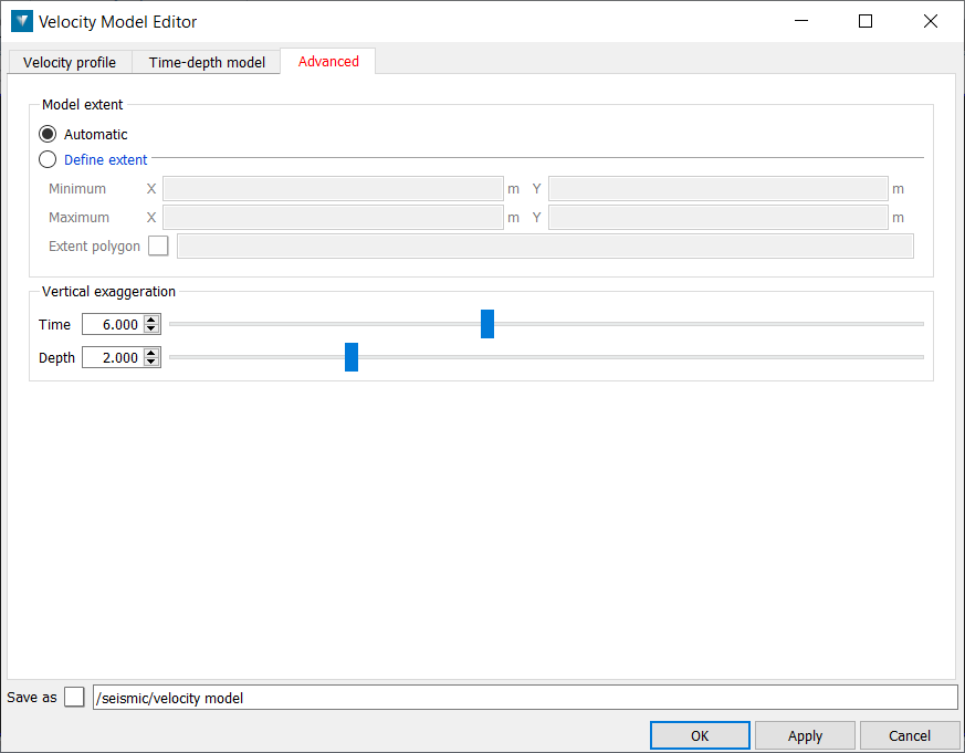
The Model extent defines the XY extents of the velocity model. Geometry outside of these extents cannot be converted by the velocity model.
-
Automatic updates the extents automatically by examining the extents of the source objects used to define the time-depth model.
-
Define extent can be used to define the extent, either using a previously created polygon, or with explicit coordinates.
Vertical Exaggeration can be applied to the views in the Time-depth model tab if required to emphasise variation in flat lying horizons.
When complete, click OK to apply the changes to the velocity model.
Note: Seismic which has been associated with a velocity model will be automatically adjusted when the model is edited.
Depth Conversion
Depth conversion is used to apply a velocity model to seismic data and any associated interpretations, to convert data in the time domain to depth. It can also be used to align seismic data with topography if required. This will remove any part of the seismic lying between the seismic datum and the earth surface.
-
Select the required objects in the Explorer window.
-
Select Seismic > Velocity > Depth conversion.
-
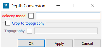
Select a Velocity model by dragging and dropping a Velocity model into the field using the middle mouse button. Velocity models are stored in the seismic container. Dragging and dropping seismic data into the field, or selecting one in the View window, will select the velocity model that has been applied to that section.
-
If required, drag and drop a triangulation surface which defines the Topography into the field, using the middle mouse button. Select Crop to topography to remove any part of the seismic section which lies above the topography surface.
-
Select OK to apply the velocity model.
Note: Seismic data which has been associated with a velocity model will be automatically updated when the velocity model is edited. However, any interpretations which have been associated will need to be updated manually.
Note: Seismic data can be coloured by either the average or instantaneous velocity at each point by right-clicking the seismic in the view and selecting from the colour options.
Example
-
Create a Stratigraphy which defines the horizon sequence.
-
Create a Velocity model containing the depth information. A new Velocity model can be created using Seismic > Velocity > Velocity model editor, or by right-clicking an existing Velocity model. Give the Velocity model a name in the Save as field .
-
Drag and drop the Stratigraphy into the Stratigraphy field using the middle mouse button. Select the horizons which will be used in the Velocity model from the list
.
-
Open the Time-depth model tab and select a horizon from the Define top of... drop down menu.
-
Select Add time depth-points from drillholes. Drag and drop the drillholes and seismic sections which will be used to define the Velocity model into the table.

-
Select the Table, Field and Horizon in the drillhole database which contains the horizon selected in step 4. If the horizon names in the Stratigraphy
 match the drillhole horizons, the associations will be made automatically. Press OK when complete.
 -
Select the first row in the Time-depth model table to select the first drillhole. The closest point on the seismic sections to the drillhole will be highlighted in the left window.
-
Select the point on the seismic in the highlighted area which correspond with the top of the horizon selected in step 4.
-
Select the next row in the table to view the next drillhole. Repeat until depth information is provided for all the drillholes.
-
Repeat steps 4-9 for all the required horizons.
-
Once all the horizons have their depths defined, select OK or Apply to complete the Velocity model.
-
Select the required data, then select Seismic > Depth conversion.
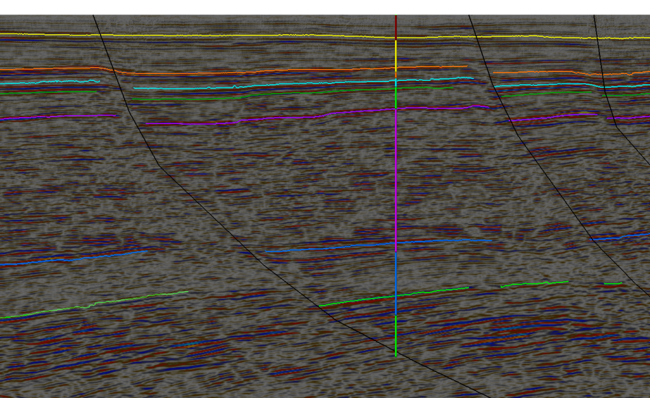
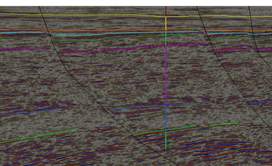
The above example shows an interpreted seismic section with a uniform Velocity model applied. The seismic section and the interpretations have been selected so they can be depth converted. The nearly drillhole has been used to provide the horizon depths used in the Velocity model.
-
Drag and drop the Velocity model into the field provided.
-
Select a topography
 to crop the seismic sections to, if required, then click OK or Apply to depth convert the selected data.
Depth converting the seismic section below has adjusted the interpreted horizons on the seismic to be level with the corresponding intervals on the drillhole.
