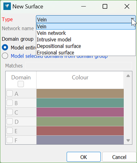
Depositional and Erosional surfaces
There are two types of contact surfaces that can be used in Modelling Manager for geological modelling.
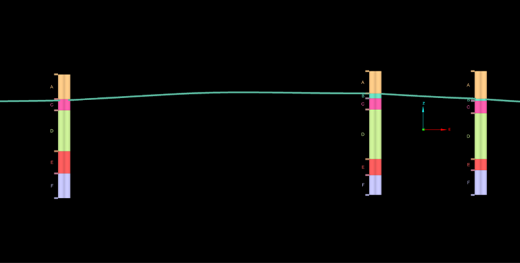
Depositional Surface
A depositional surface is defined by a single set of contact points between two domains. These contact points can be located either above or below the unit being modelled.
Depositional surface volumes cannot cut into an underlying older unit. They always sit on top of older units—similar to how sand dropped onto a floor rests on the surface without removing any part of it.
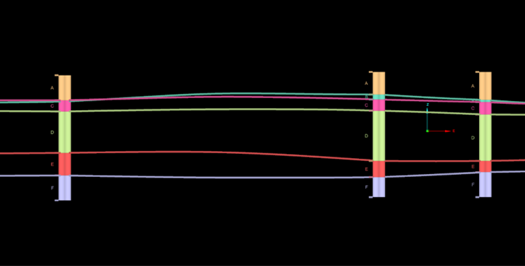
Erosional Surface
An erosional surface is also defined by a single set of contact points, located either above or below the unit being modelled.
Unlike depositional surfaces, erosional surface volumes can cut into underlying older units, similar to how waves erode a beach.
Depositional/Erosional Specifications
This is what the depositional/erosional specification panel looks like:
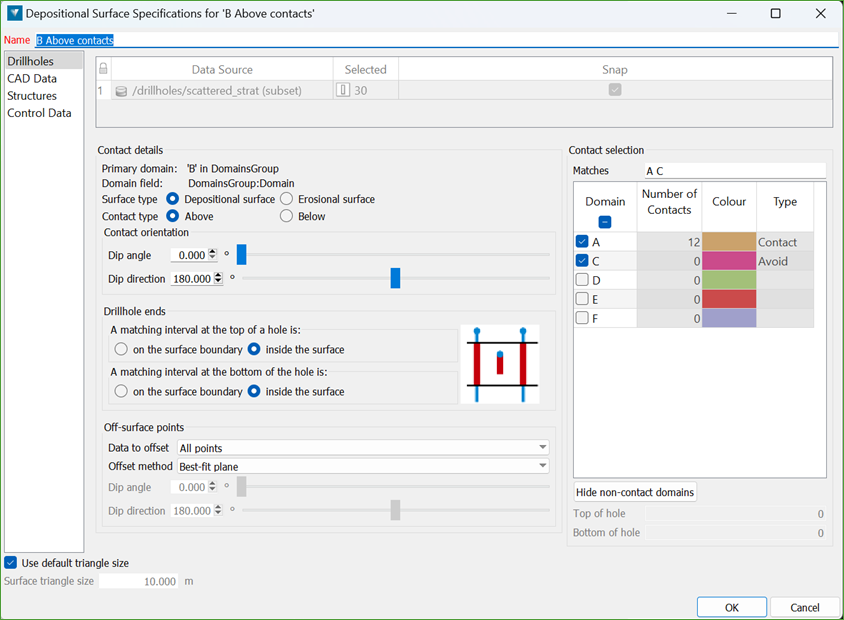
Drillholes
Primary domain
The primary domain defines the domain intervals used to generate the contact surface.
The primary domain and domain field are set when adding the surface to the Chronology.
Surface type
This allows you to toggle between using the surface as a depositional contact or an erosional contact. However, this does not change the surface that is generated, only how it is used in the geology solid processing.
Contact type
This defines whether the contact point will be at the top (above) or bottom (below) of the primary domain interval, relative to the plane defined by the contact orientation.
Contact orientation
The contact orientation lets you define a custom reference plane for the relative ‘up’ direction. This helps find contacts above or below the primary domain. The contact orientation is calculated to be normal to the reference plane. The default orientation is horizontal (i.e. vertical contact orientation), but you can set a custom orientation for more complex geology.
Drillhole ends
Same as in the Implicit Modeller panel, this setting defines whether a contact point is used or ignored if the primary domain interval is at the top or bottom of the drillhole and ends in the domain without a clear contact.
Off-surface points
To generate an implicit surface from contact points (where a SignedDistance value of 0 is on the surface boundary), off-surface points need to be created. These points are assigned positive SignedDistance values (outside the surface) and negative values (inside the surface) to enable solving the (Radial Basis Function) RBF.
Data to offset
This defines which input points are projected to generate off-surface points. Options are:
-
All points – all input points will generate off-surface points.
-
CAD and structures only – only CAD and structure points will generate off-surface points..
Offset method
This defines the orientation of the plane perpendicular to which off-surface points are projected. Options are:
-
Best-fit plane – calculated from the input points.
-
Defined plane – a user-defined plane is used for projection.
A defined plane can be a better choice if the generated contact surface does not follow the expected orientation. This often happens when there are few drillholes or when contacts form a line. In such cases, using a ‘Constant’ interpolant polynomial with a defined plane can give better results than a ‘Linear’ polynomial.
Contact Selection
When generating surface points, you can assign two types to surrounding domains:
-
Contact: Use this for intervals directly adjacent to the primary domain (above or below, based on your settings). Contact points mark the interface between the primary domain and its neighbours, guiding surface construction along those boundaries.
-
Avoid: Use this when the primary domain is absent; for example, where it has been eroded or never deposited. You can select a different domain (with no shared contact) to be avoided. An avoid point is placed inside that interval, forcing the surface to pass through it. During chronological boolean operations, this ensures older units pinch out the primary domain, producing realistic lensing or thinning where the primary domain was eroded or did not accumulate, while maintaining continuity between adjacent solids.
Outputs
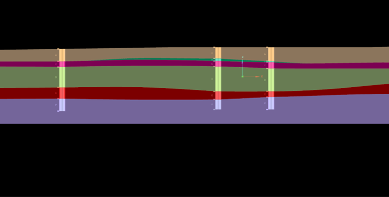
The contact surface is the main output from Chronology modelling of a Depositional or Erosional surface. It appears at the root level of the <surface name> container. This surface has been clipped to fit the bounding box and topography.
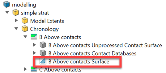
To see what was used to generate this surface, you can expand the grey container above.
Contact Databases
Two drillhole contact databases are generated:
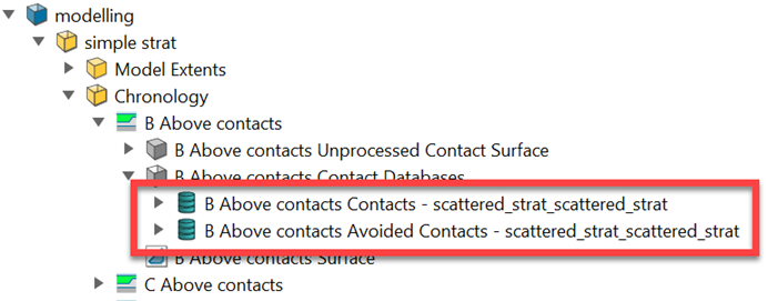
-
<surface name> Contacts - <source drillhole database name>contains the contacting points downhole. -
<surface name> Avoided Contacts - <source drillhole database name>contains the avoiding points downhole. This database is only created if any “avoid” contacts have been defined.
Both of these contact databases can be loaded into the view.
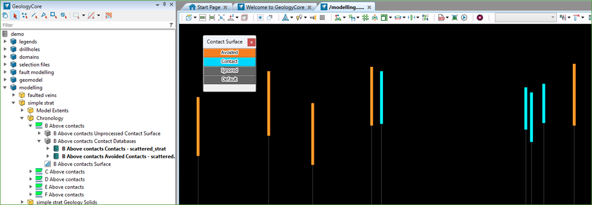
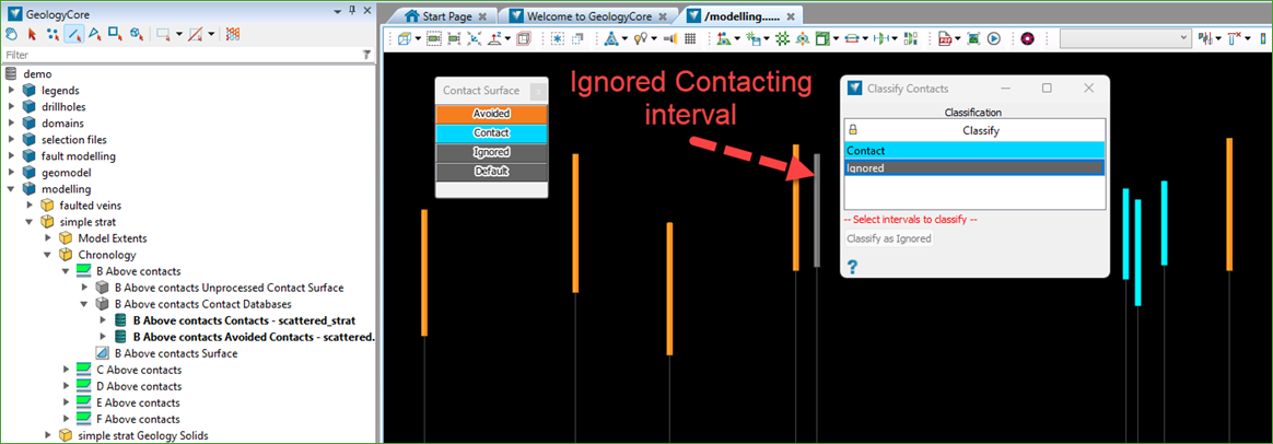
The Modelling > Modelling Controls > Classify Contacts tool can be used to select intervals (using Edge Select mode) from either the Contacts or Avoided Contacts databases.
You can then set these intervals as Ignored, meaning they will be excluded the next time the surface is remodelled.
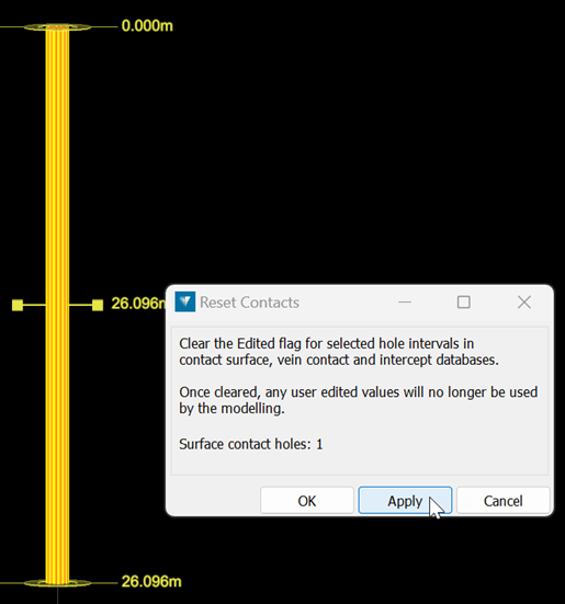
If the automatically generated pinch-out depth for an Avoid contact doesn’t produce the desired result, you can manually adjust it.
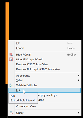
To change the depth of the pinch-out point, right-click on the Avoid Contact in the view and select Edit.
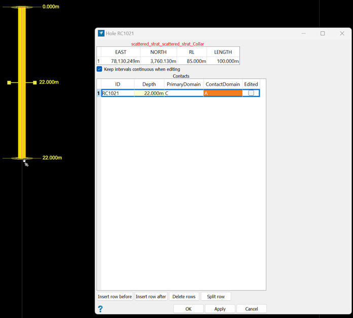
You can use the middle mouse button to grab the yellow disc at the current depth location and drag it up or down to the desired position on the drillhole.
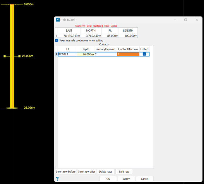
Alternatively, you can manually enter the desired depth in the Depth cell in the panel.
Once the depth has been manually adjusted, the Edited flag will be set for that drillhole’s Avoiding interval. This ensures that the manually defined depth won’t be overwritten the next time the surface is remodelled.
The Modelling > Modelling Controls > Reset Contacts tool allows you to reset previously edited intervals back to their original values. This includes intervals that were flagged as Ignored as well as those that were manually adjusted.
Resetting clears the Edited flag on all affected intervals. As a result, all intervals will be used the next time the surface is remodelled.
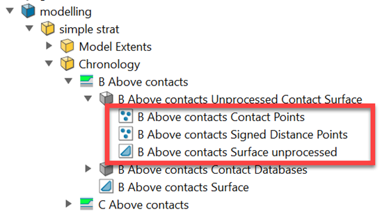
Unprocessed Contact Surface
The <surface name> Unprocessed Contact Surface container includes the following objects:
-
Contact Points – These are the contact points extracted from the drillholes and used to generate the surface.
-
Signed Distance Points – This includes the contact points and the off-surface projected points, as defined in the Off-surface settings panel. These points are passed to the RBF engine to generate the surface.
-
Surface unprocessed – This is the contact surface before it has been clipped to the bounding solid. It is the version used in the boolean operations during Geology Model processing to build the solid volumes.
