Generate Domained Samples
The Samples Manager enables a streamlined way of performing compositing of drillhole intervals for use in downstream Exploratory Data Analysis (EDA) and estimation processes. The tool facilitates drillhole compositing by averaging the original grade values (assays) in a drillhole database into pre-specified lengths and/or regions (e.g., domains). This process homogenises the data scale across the site, improving the accuracy of geostatistical methods used in resource estimation and simulation, and compensates for incomplete sample intervals.
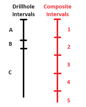
In Samples Manager, composites are calculated using a mass-weighted average, or a length-weighted average if specific-gravity data is unavailable. In simplified terms, composites are created in GeologyCore as sample point-sets, with one point for each composite interval. These points include composited grade (assay) values and additional attributes such as hole composited, thickness, top and bottom intercepts, etc. These point-sets can be exported as composite databases for use in Vulcan and the Vulcan Data Analyser (VDA).
Compositing can be done for various purposes, including obtaining representative values for ore body intersections, lithological or product composites, regular length down-hole composites, bench or section composites, high-grade composites, and minimum length and grade composites.
The Samples Manager tool is located under the Modelling section of the Modelling ribbon tab.
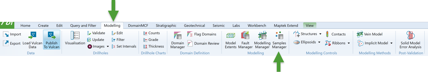
Selecting this option will open the Samples Manager panel, which has multiple tabs.
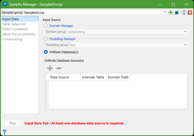
Note: You need to work through the tabs in order, from top to bottom. The lower tabs will stay locked until you have correctly filled in the higher tabs. If something is wrong, a message will appear at the bottom of the panel in a warning colour, showing the errors. Once these errors are fixed, the Run button will be available. The panel updates in real time, so there is no Cancel button. You can close it at any time, and any changes you have made will be saved. If you reopen the panel, your settings will be restored. You do not have to fix all errors or finish setting it up before closing. You can also undo or redo changes using the usual GeologyCore controls.
Samples group
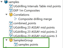
A Samples Group object in the Samples Manager acts both as a container for storing data and as a set of specifications. These objects are created within the Geology Core system’s samples container.
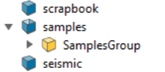
The Samples Group container stores the composite point-set data generated when using the associated specifications of that Samples Group. Essentially, it holds the data and rules for how samples are managed within the system.
Samples group controls
The drop-down list contains all the available Samples Group objects. By default, it will show the last Samples Group that was in use when the panel was closed. If you're opening the Samples Manager panel for the first time in a project and no Samples Group objects have been created yet, a new, empty Samples Group object will automatically be created, named SamplesGroup by default. You can rename or modify this object using the controls provided in the panel.
|
|
Create a new samples group |
|
|
Make a copy of the current samples group |
|
|
Rename the current samples group |
|
|
Delete the current samples group |
Samples Manager Workflow
The workflow in the Samples Manager panel follows a top-to-bottom order through the tabs, as shown on the panel's side bar. Each tab requires input to complete the specifications, except for the Value Pre-processing tab, which can be skipped. While the Field Correlation tab is usually auto-filled, it is important for users to review it before moving forward in the setup process.
Follow these steps to get started with Samples Manager:
-
Input Data
The input data for producing composites comes from drillholes in one or more databases. You can choose the data from these databases in three ways:
-
Domain Manager: By using the database selections made for an existing Domain Group.
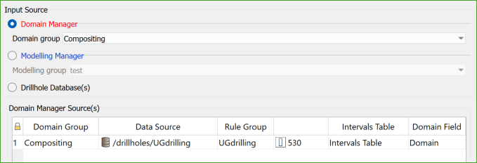
Specify a name for the domain group. The drillhole databases and the associated holes selected within them will be identified and used as the input data for this domain group.
-
Modelling Manager: By using the database selections made for the Domain Group(s) used by an existing Modelling Group.
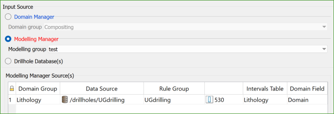
Specify a name for the modelling group. The system will identify the domain groups linked to this modelling group, and the associated drillhole databases and holes will be selected and used as the input data.
-
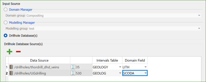
Drillhole Database(s): By selecting the databases or specific subsets of holes from the explorer.
Specify the drillhole database(s) or the 'interval' table that you want to use for each source. The holes within them will be used as input data.
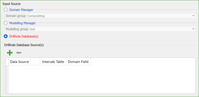
To select a database or a subset of drillholes, choose the desired item from the explorer and click the "Green Plus" button above the data grid. You can also use a selection group object to create a subset of holes, and then drag and drop the selection directly onto the data grid.
The Samples Manager can only composite drillholes from one input source at a time (either Domain Manager, Modelling Manager, or Databases), but it keeps specifications for each source type separate in the Samples Group object. While you can store specs for multiple source types in one Samples Group, it is better to have separate specifications for each task for easier auditing.
Note: If no Domain Groups or Modelling Groups exist in the project, the options to select them will be disabled. This ensures that only valid selections are made based on the available groups. When you create a new Samples Group, the system will automatically pick the first available Domain or Modelling Group. By default, it selects the Domain Manager as the data source. If the Domain Manager is not available, it will use the Modelling Manager. If neither is available, it defaults to Drillhole Database selection.
-
-
Table Selection
The Table Selection tab has two main functions:
-
Grade Data Specification: It allows you to specify which tables in each database will provide the grade (assay) data for compositing.
-
Database Hierarchy Specification: When multiple databases are associated with the source, this function defines the database hierarchy, specifically selecting which database will be the Master source. The Master Source is used by the Samples Manager to establish the primary attribute names and data types. This order can be different from how the databases are arranged in the Domain Group or Modelling Group objects. The sequence of databases is adjusted using the controls located above the upper data grid. More details about the ‘master’ database can be found on the Field Correlation tab.
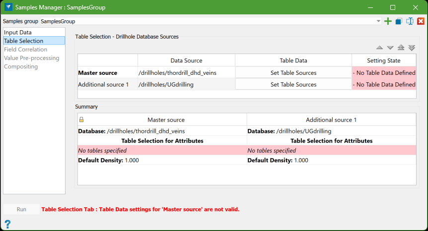
After selecting to use a Drillhole Database(s) on the Input Data tab, the Table Selection tab will display a data grid showing the source databases. Each row in the data grid has an action button labelled Set Table Source, which you can click to specify the tables and/or LAS files that will provide the grade (assay) data for compositing.
Below the data grid, there is a Summary section that displays the details for the databases. This summary makes it easy to review the current specifications without needing to navigate through tabs.
Set Table Source
To set the sources of the grade values, which will be attributes of the composite intervals for each database in the source type, press the Set Table Sources button on the corresponding row in the data grid.


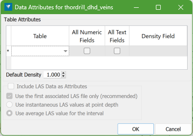
When you click the button, the following panel appears. This panel allows you to select the table(s) containing grade or assay values linked to the selected drillholes. If LAS data is associated with the selected holes in the project, you can optionally include that data as well.
This process generates a mass-weighted average for numeric fields and a mass-weighted majority for text fields related to each interval, which will then be assigned to the points created for that interval.
Table Selection
From the drop-down list of table names in the database, select all tables that contain grade data. For example, in the database, the GEOLOGY table may be selected for grade/assay values.
The behaviour of this selection is as follows:
-
You can select as many tables as needed.
-
If the grade data is on the same table as the Intervals Table (set on the Input Data tab), that table can be selected here too.
-
By default, Samples Manager will use all available numeric and text fields from a table, though you can deselect either category by unchecking its box. If no data exists in a category, that column will be disabled.
-
Certain field types that are not grade values, such as interval depths and domain names, will be excluded automatically.
-
If density data has been recorded for the intervals, specify the relevant RD/SG field in the Density Field column. This allows for more accurate mass-weighted averaging of composite data instead of simple length-weighted averaging.
-
You must also enter a Default Density value below the data grid, which will be used when density data is missing for any interval.
LAS Data
-
Include LAS Data as Attributes: If any selected holes have LAS data, this option will be enabled. Select this option to add LAS values as attributes to the created points.
-
Use the first associated LAS file only: If drillholes have multiple associated LAS files, choose this option to use only the first one, as recommended. If more than one file has the same curve name, the first occurrence will be used, and later ones ignored. Uncheck this option only if you are certain the curve names are unique across all files.
-
Use instantaneous LAS values at point depth: Select this option to use instantaneous LAS values calculated at the midpoint of the composite interval.
-
Use average LAS values for the interval: Select this option to use averages LAS values calculated from all data points within the composite interval depth range.
Note: You can use an instantaneous value for faster processing, but for greater accuracy, it is recommended to use the full-weighted average.
-
-
Field Correlation
Once valid entries are made, the Field Correlation tab will be enabled. This tab will be auto-populated based on the Table Selection settings. If no user action is needed, as in the example case, the other tabs will also be enabled.
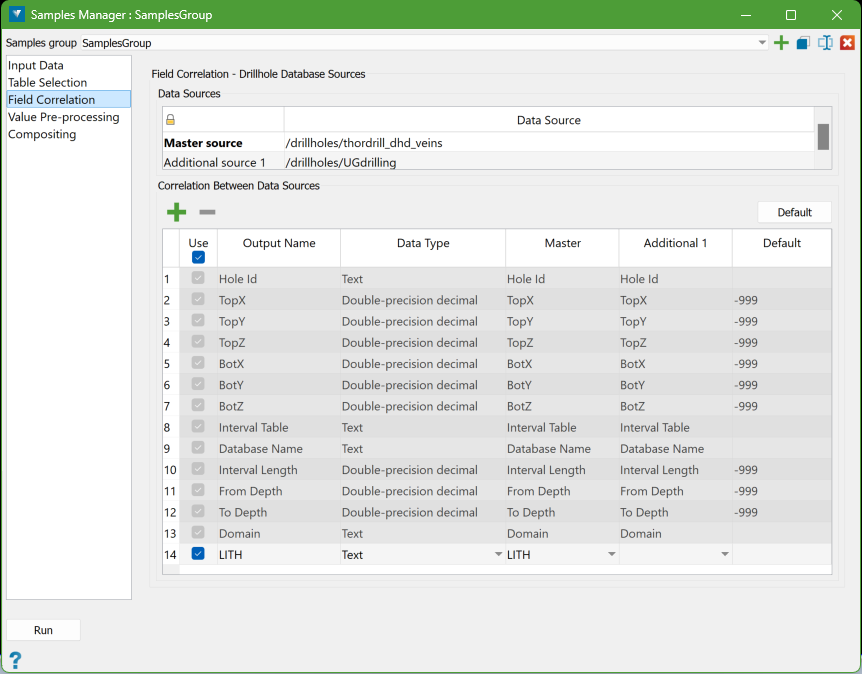
The Field Correlation tab displays the attributes that will be added to the composite points and allows the user to adjust how variables are correlated between different data sources. This means matching variables from the grade (assay) table of additional sources with those from the Master source. The auto-correlation tool will attempt to match variables by name, but user adjustments may be necessary if inconsistent naming has been used, such as when working with older, historical data.
The attributes displayed on the Field Correlation tab fall into two categories:
-
System Variables: These are essential variables required when exporting a composite database from the created composite points. In the example above, the first 13 attributes listed in the data grid are system variables that cannot be edited or changed. They are included for completeness and clarity. While most are self-explanatory, a few require additional details:
-
TopX, TopY, TopZ: The coordinates of the top of the composite interval, interpolated from survey data.
-
BotX, BotY, BotZ: The coordinates of the bottom of the composite interval, also interpolated from survey data.
-
Interval Length: The length of the composite interval.
-
From Depth: The downhole depth at the top of the composite interval.
-
To Depth: The downhole depth at the bottom of the composite interval.
The mid-point coordinates (MidX, MidY, MidZ) are stored as the actual coordinates of the composite points generated during the compositing process. These will become the
MidX, MidY, MidZcolumns in the exported composite database.
-
-
Grade Variables: The remaining item(s) on the data grid are the grade/assay variables (both numeric and text) sourced from the grade/assay tables selected for each source on the Table Selection tab. These attributes are fully editable and displayed in their standard format on the data grid. There is effectively no limit to the number of variables that can be used as attributes.
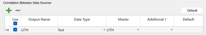
In the above example, there is an additional attribute LITH derived from the assay tables, and the attribute names have been automatically taken from the Master source by default.
Master Source
The Master Source is crucial as it provides the initial attribute names, data types, and the initial list of attributes. It is important to carefully choose the Master source database, ideally before selecting the assay tables.
In the provided example, thordrill_dhd_veins database is the Master source and has less variables than the database. If the roles were reversed and UGdrilling were the Master source, the resulting list of attributes would be significantly longer. While additional items can be added or removed manually if necessary, it is generally easier to set the Master source correctly from the beginning when a complete set of variables is required.
Editing Grade Attributes
All parameters of the grade attribute correlation rows can be edited.
Use
The Use column features a checkbox that allows you to disable an attribute without removing it from the specifications. This is useful if you temporarily need a reduced attribute composite dataset; you can turn off the unwanted items while keeping them available for future use.
Output Name
The output name is arbitrary and is initially based on the field names from the Master source database. You can edit this name as needed, but it must be unique, and this will be verified.
Important: Some applications that will export this data may have specific naming requirements. To ensure compatibility with external programs, it is best to use alphanumeric characters, starting with a letter, and to avoid spaces in the name. Characters like underscores and hyphens are acceptable within the name. Following these guidelines will help ensure broader compatibility.
Data Type
The data type can be selected from a list of options:
-
Text
-
Double-precision decimal
-
Single-precision decimal
-
Integer
-
Boolean
-
Date/Time
It is crucial to choose a data type that is compatible with the fields being correlated from all sources to ensure accurate data processing. To know more about incompatible data types, click here.
Master
The Master source can be selected from a drop-down list of available fields from the Master source. This field typically does not need to be changed for existing rows, but when adding new rows, you must select a name. It is valid to leave a field name empty, meaning that nothing from this source will provide the attribute value when compositing.
Note: If multiple assay tables are nominated for a database, non-unique field names will be qualified with their table names in the format <FIELD_NAME>_<TABLE_NAME>.
Additional 1
For each Additional source, you can select the corresponding field to be correlated. The automatically generated correlation might use the wrong field or miss a match due to differing names (e.g., S for sulphur in one database and S_PPM in another). An empty correlation is valid, but if no sources have a matching field for an attribute, it may be better to delete that row.
Default
The default value is used only when applying the attribute to the composite interval point, if no value for that attribute is available. It is not utilised for statistical weighting purposes (see the Value Pre-processing tab for handling missing items in calculations). This default value is what will be displayed in the output when no composite attribute value can be calculated and is set by default to be compatible with expected values in Vulcan composite databases, although you can edit it as needed.
Adding and Deleting Grade Attributes
There are two controls located above the correlation data grid that allow you to add or delete the attributes.

Add control Add new attributes to the data grid. 
Delete control Remove existing attributes from the data grid These controls make it easy to customise the attributes you want to include in the composite intervals.
Adding
By default, all items available in the Master source will be included as attributes. However, there may be additional source items without equivalents in the Master source that remain unused. To utilise these items or to restore an incorrectly deleted row, you can add a new attribute.
To do this, press the Add control
, which will create a new empty row at the end of the data grid as shown below: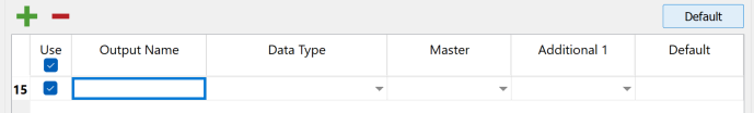
Fill in all of the relevant columns for this attribute.
Note: Since there is no corresponding field value in the Master source, only the additional source column will have a correlation. This means you will need to rely solely on the additional source to provide the necessary data for that attribute.
Deleting
You can delete unwanted rows, but it is generally better to just turn off the Use flag instead of deleting them, as refreshing the correlation will restore the deleted rows. If you do want to delete a row, click on any cell in that row to select it, and then click the Delete control
to remove it.Unmatched and Incompatible Data Type
In our example, we have a situation where the field name SU appears in both sources but has incompatible data types: the Additional Source 1 has it as a Text field, while the master source has it as a Double-precision decimal. If this mismatch occurs, an error warning will be displayed as shown below.
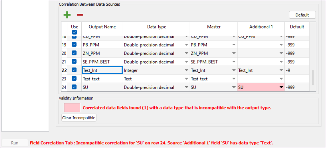
To resolve it, use one of the following options:
-
Clear all incompatible entries: Press the Clear Incompatible button to remove the incompatible entry from the additional sources, allowing only the master source to provide this data.
-
Clear an incompatible entry: Manually clear the field(s) for the Additional Sources not wanted (or which can not be made usefully compatible). Rather than clearing all incompatible sources, this allows for some to be removed while allowing for compatible data types to be selected for the others.
-
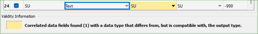
Change data type: Change the data type to a compatible data-type that will support the information from all the remaining sources selected to contribute to an attribute. Where the field data-type differs from, but is compatible with, the output type these fields will be coloured as shown below. This is not an error, just an indication for information.
Note: Changing the output data type to Text would make it compatible with any source data type (all of which can be converted to text) but this will not be very useful for numerical attributes.
-
Delete the row: Delete the row entirely if you choose not to use that attribute.
Default
Sometimes, you might need to refresh the correlation between your data sources. Ideally, you should set the hierarchy of your sources (Master and Additional) before selecting their tables. If you realise later that they are in the wrong order, changing the hierarchy will not add more attributes to your list. This is intentional, so you do not lose any changes you have already made. However, if you want to see what the attributes would look like if you had set the hierarchy correctly from the start, you can press the Default button. This will reset the correlation to the automatically generated state based on your current settings.
-
-
Value Pre-processing
The Value Pre-processing tab allows you to modify values read from the database based on certain rules, but making changes is optional. You can adjust the values for any, all, or none of the attributes without affecting the actual database—only the values used from the database are modified. This tab looks similar to the Table Selection tab, featuring a Data Source grid at the top and a Summary grid below it.
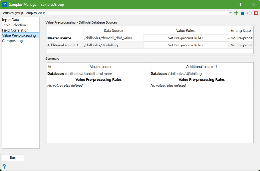
Set Pre-process Rules
You can set specific rules for modifying values for each database individually, allowing for different rules based on the source of the attribute.
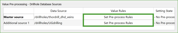
To create these value pre-processing rules, click the Set Pre-process Rules button next to the corresponding database, which will open a panel for defining the rules.
These rules are called modifiers and work similarly to those used in the Domain Manager, making it easy for users familiar with that tool to understand.
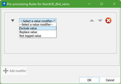
On the panel, choose a modifier type from the drop-down list to define how to adjust the values. The three available Value Modifiers are:
-
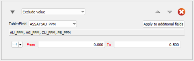
Exclude value: This will ignore certain values from being considered.
-
Replace value: This will substitute a specified value with another.
-
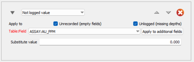
Not logged value: This will identify values that are not recorded or available in the dataset.
After selecting and setting up the first modifier type, the Add Modifier button will be enabled. Pressing it will create another empty modifier section below the first, allowing you to set additional modifiers as needed. You can continue adding modifiers without any limit.
Important: It is necessary to define the modifiers in the correct order since they are processed sequentially. For instance, having a Replace value modifier for AU_PPT set to zero after an Exclude value modifier for AU_PPT set to zero is ineffective because the latter would have already removed that value from consideration.
Each modifier will have controls at the top right to set the order:

-
Arrows allow you to change the modifier's position in the sequence—moving it up or down. If a modifier is already at the top or bottom, the corresponding arrow will be disabled.
-
Cross is used to remove a modifier from the list; however, the last modifier cannot be deleted, only cleared.
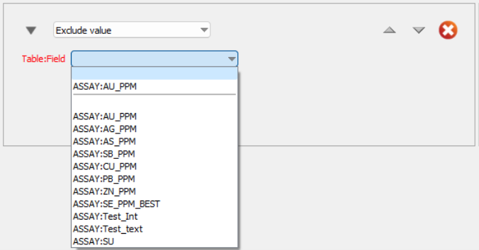
Exclude value
Values excluded by this modifier will not be considered when calculating weighted composite values.
Table:Field - Choose a valid field from the table(s) for the modifier.
Condition - Define the condition that will trigger the exclusion based on the field type:
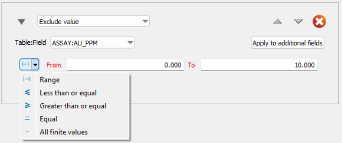
-
For Floating Point Numeric Fields:
-
Range: Exclude values within a specified range.
-
Less than or equal to: Exclude values less than or equal to a specified value.
-
Greater than or equal to: Exclude values greater than or equal to a specified value.
-
Equal to: Exclude values that are exactly equal to a specified value.
-
Not Empty: Exclude values that are not empty (not-logged).
-
-
For Text Type Fields:
-
Text Match: Exclude values that match specified text or from a legend (multiple values can be comma-separated).

-
-
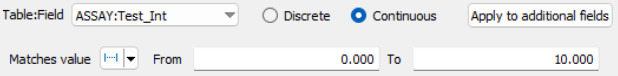
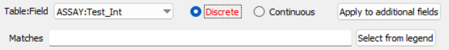
For Integer Numeric Fields:
-
Continuous Value: Options are the same as floating point numeric fields (range, less than, greater than, equal to, not empty).
-
Discrete Value: Match values similar to text fields (specific matches or legend values).
-
Apply to additional fields:
If the same rule applies to multiple fields, use the Apply to additional fields button to select them all at once. The following panel is displayed to select additional fields.
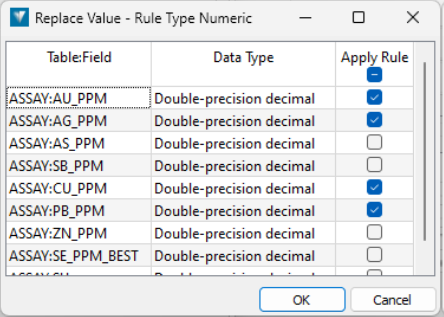
When multiple fields are selected, the modifier will list all applicable fields.
Replace value
The Replace value modifier works just like the Exclude value modifier, but with one key difference: instead of ignoring certain values, you get to choose what to replace them with.
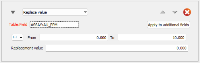
For example, if certain values in your data match a condition (like being too high, too low, or exactly a certain number), you can replace those values with a different one that you specify.
When the system calculates composite values (combined data for analysis), it will use the replacement value you provided instead of the original one. However, you should be careful when using this, as replacing too many values might distort the results and affect the accuracy of your estimates.
Not logged value
The Not logged value modifier works a bit differently from the Exclude and Replace value modifiers, as it deals with missing or unlogged data.
There are two types of "not logged" data:
-
Unlogged data: The data is completely missing from the assay table, meaning no sample was analysed or the record was lost.
-
Unrecorded data: The sample was taken, but a particular test was not performed or the result was lost, leaving the field empty.
In the first case, the system will have gaps when calculating averages. In the second case, the missing value can't be used. This modifier allows you to substitute a value in place of missing data in either or both situations, ensuring smoother calculations.
To apply the Not logged value modifier, you need to check the boxes for the type of missing data (either Unlogged or Unrecorded). If neither box is checked, the rule won't do anything, and this will be flagged in the Summary.
The process for selecting the condition for "not logged" data works the same way as the other modifiers. Similarly, the process for specifying the substitute value follows the same method as the replacement value in Replace value modifier.
When calculating weighted composite values, the system will use the substitute value provided. By default, "not logged" values are ignored as if they were excluded.
-
-
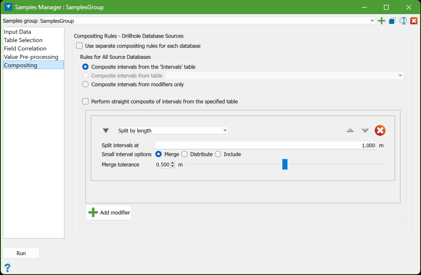
Compositing
The Compositing tab allows you to define the rules for compositing drillholes.
It can be used in two ways:
-
Single Set of Rules for All Databases
-
You can create one set of compositing rules that will apply to all the databases specified in the Input Data tab.
-
This approach is simpler and effective if all databases have a similar structure.
-
Some compositing rules require a specific table and field, so for a common rule to work, these fields must exist in all databases and contain similar data.
-
-
Separate Rules for Each Database:
-
If the databases have different structures, you can create separate compositing rules for each one.
-
To do this, tick the checkbox at the top of the tab to enable individual rule definitions.
-
Note: Defining common rules simplifies the setup, but if database structures differ significantly, individual rules may be necessary.
Single Set of Rules for All Databases
Uncheck the option Use separate compositing rules for each database on the top of the panel. This allows to define a single set of rules for all source databases.
Composite intervals from the 'Intervals' table
-
This option uses the domain intervals defined by the ‘Intervals’ table from the databases selected in the Input Data tab.
-
These intervals are the main source for applying compositing modifiers or for generating a straight composite.
Composite intervals from table
-
Allows selection of a different table from the database for compositing.
-
If selected, a combo-box shows available downhole tables, but only those common to all databases will appear when using common rules. If no tables are common, this option is disabled.
-
Useful for direct compositing of specific tables, such as the ASSAY table.
Composite intervals from modifiers only
-
This option applies compositing modifiers directly to the entire length of the drillhole rather than specific intervals from a table.
-
If this is chosen, a straight composite cannot be applied, and compositing modifiers are required.
Straight composite
-
To create a straight composite from the selected intervals source, select the option Perform straight composite of intervals from the specified table, which disables the section for adding modifiers.
-
This means the intervals from the selected source will be used directly for the composite without any modifications.
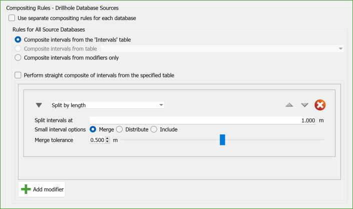
Composite Modifiers
These modifiers are similar to the Value Pre-processing rules and are a subset of the modifiers available in the Domain Manager. They control how the composite data is created.
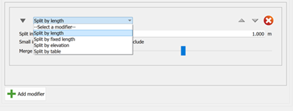
The modifiers available for compositing are:
-
Split by length: Divides intervals based on a specified length. Any remaining part of an interval shorter than this length is handled based on user selection.
-
Split by fixed length: The entire length of the hole is divided into new intervals of a fixed length that you specify.
-
Split by elevation: Creates splits at a specific elevation and at multiples of that elevation, essentially forming sections (or benches) of the composite.
-
Split by table: Divides the intervals based on specified table intervals. A secondary table can fill in gaps where intervals are missing in the primary table.
Each modifier is applied in a specific order to the intervals. The order is important because applying a modifier out of sequence can make previous changes irrelevant.
Note: When using modifiers to define intervals without a table, the first modifier will only receive one interval that starts from the top of the hole and ends at its total depth.
Separate Rules for Each Database
To define separate rules for each source database, you need to select the option Use separate compositing rules for each database. Once this option is chosen, a new panel will appear.
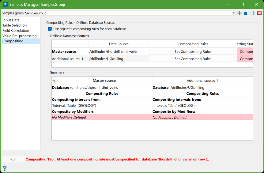
This panel is structured similarly to the ones found in the Table Selection, Field Correlation, and Value Pre-processing tabs. It consists of a Data Sources grid at the top and a Summary grid below, which are both used for managing the compositing rules.
In the Data Sources grid, you will find a button labelled Set Compositing Rules.
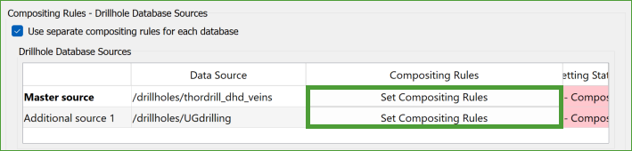
When you click this button, it opens the Compositing Modifiers panel, allowing you to define specific rules for each source database. This process is similar to how you would set rules if you were working with a single set of compositing rules.
Running the Composite
Once all the specifications are valid, the panel status line should display no warnings. This indicates that everything is set up correctly. When there are no issues, the Run button will become enabled, allowing you to proceed with the compositing process.
To create the sample points, click the Run button. Once the process is successfully completed, a toast message will appear confirming the action.

You can then locate the resulting composite points within the specification container of the samples section in the explorer.