Appearance
The following table describes the tools in the Appearance section of the Seismic tab.
| Tool | Description |
| Visualisation | Changes the way seismic data is displayed in the View window. |
| Bright Spots | Adjusts the translucency level of seismic data below a specified value. |
| Settings | Re-imports SEG Y seismic data to enable the import options to be modified. |
Visualisation
Visualisation is used to change the way seismic data ![]() is displayed in the View window.
is displayed in the View window.
Note: The seismic data is not altered, only the way it is displayed.
-
Select the required seismic data
 .
. -
Select Seismic > Visualisation.
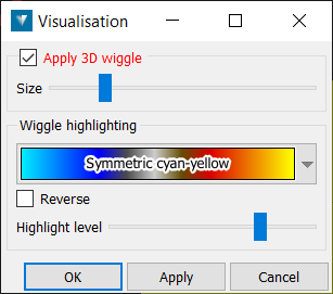
The Apply 3D wiggle check-box toggles the display of the amplitude perpendicular to the section, allowing anomalies to be more easily identified. The Size slider can be used to adjust the exaggeration of the wiggle.
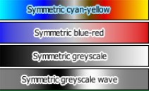
Seismic can be displayed in colour or in greyscale by selecting a colour scheme from the drop-down menu.
The Reverse check-box reverses the selected colour scheme.
The Highlight level slider is used to alter the level of colour that is applied to the seismic data.
Bright Spots
Bright spots is used to adjust the translucency level of seismic data ![]() below a specified value to highlight anomalies.
below a specified value to highlight anomalies.
-
Select the required seismic data.
-
Select Seismic > Bright spots.
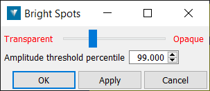
The Amplitude threshold percentile defines the output result below which the display can be adjusted, between Transparent and Opaque, using the slider.
Settings
Settings is used to define how SEG Y seismic data is imported. Data may be re-imported to change the level of detail present, change how the trace coordinates are acquired or to apply/remove cropping of the data.
The default (Automatic) settings in this panel are correct for seismic data that strictly follows SEG Y standards, however the panel settings may be used to specify any variations to the SEG Y standard that exist in the file.
Note: The seismic data must still be present in the location it was originally imported to modify the settings. If the seismic has been moved to a different directory, a prompt will appear where the new directory can be entered.
-
Select the seismic data. More than one data file may be re-imported at once.
-
Select Seismic > Settings. The panel is displayed automatically when importing seismic data.
Resolution
The Resolution tab is used to decrease the level of detail imported, to facilitate viewing large quantities of seismic data and avoid problems caused by limited memory. This is done by reducing the overall point count of the data. The detail slider may be used to specify the level of detail required to be imported.
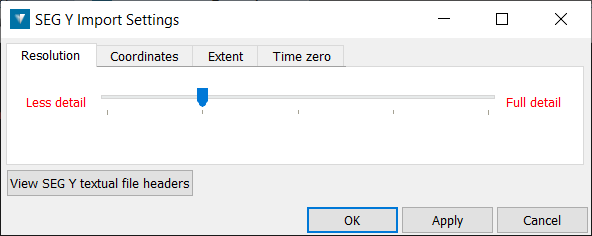
View SEG Y textual file headers
The View SEG Y textual file headers button is used to display the textual file header, which contains up to 40 lines of text describing the seismic data in the SEG Y file. It should contain information about any unusual features in the file, such as if the delay recording time in trace header bytes 109-110 is non-zero. See Time zero below.
This information may be useful to discover whether non-standard byte offsets have been used for x and y trace coordinates, and also to display the seismic datum. Note: The seismic datum can be adjusted if required in the Velocity model editor.

Coordinates
The Coordinates tab is used to specify how the trace coordinates are acquired from the SEG Y file.
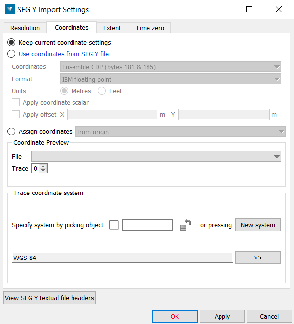
Keep current coordinate settings analyses the file and selects the most likely location for the coordinate data in the files.
If the automatic option does not locate the data on the correct coordinates, Use coordinates from SEG Y file can be used to select the correct option:
-
Ensemble (CommonDepthPoint), Source and Group are standard trace coordinate locations in the seismic data file.
-
None is used if no trace coordinates have been specified in the data - this places the data at 0,0.
-
Custom is used to manually specify the x and y byte locations within the file trace header.
Format specifies the encoding used by the trace coordinate field.
The Units may be altered if required.
The Apply coordinate scalar check-box can be used to apply the scalar value defined in the seismic data file to the trace coordinates (if required).
Apply offset can be used to move seismic data along an axis by entering an offset distance by in the X and Y fields.
If the SEG Y file does not contain any relevant co-ordinate information, Assign coordinates can be can be used to display the seismic data.
-
From Origin: Displays the first seismic trace at the origin (0,0,0) with 1m spacing between traces. This option is useful for viewing seismic with an unknown co-ordinate location
-
Using interpolation: If the co-ordinates of the start and/or end traces are known, seismic can be imported by entering the relevant information into this panel. The seismic trace will be displayed as a straight line between these two points. This option is also useful for flattening a seismic data if required.
-
Using point set: A CSV of shot positions can be used to locate the corresponding seismic section.
The Coordinate preview section displays the trace coordinates that will be applied to the data as a result of the selections made above.
Trace coordinate system may be filled out if the coordinate system is known. Assigning a coordinate system is only required when converting between systems, as the assigned system will be used as a reference. The coordinate system is often stored in the View SEG Y textual file headers. A coordinate system may be assigned at any time. Define a coordinate system either by transferring the coordinate system applied to another object, or by clicking the define system button. To transfer a coordinate system from another object, give focus to the Define system by picking object field, then either:
-
middle-click and drag the reference object into the field.
-
left-click the reference object in the View window.
Extent
The Extent tab is used to import a reduced portion of the seismic data to decrease memory use. The data region to be imported may be specified by trace and/or time.
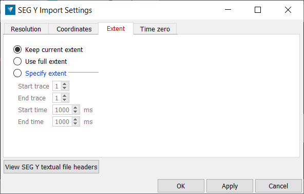
Keep current extent keeps the current settings.
Use Full Extent imports the whole extent of the seismic data.
Specify extent allows the data to be cropped by trace and/or time.
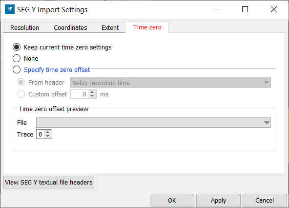
Time zero
The Time zero tab is used to specify the time in milliseconds between initiation time of energy source and the time when recording of data samples begins. If this value is non-zero, a comment to that effect should be in the textual file header.
-
Keep current time zero settings applies the current settings.
-
None applies no offset.
-
Specify time zero offset may be used to apply the standard delay specified in the data header by either Total static applied (bytes 103-104), or Delay recording time (bytes 109-110). Alternatively, a Custom offset may be applied in milliseconds.
The Time zero offset preview section displays the offset that will be applied to the data as a result of the selections made above.
