Surface Comparison
The ![]() Surface Comparison tool allows you to view the parts of the surface behind an intersecting vertical plane or between two parallel intersecting vertical planes. You can opt to display a surface from a single point in time, or compare surfaces between two points in time.
Surface Comparison tool allows you to view the parts of the surface behind an intersecting vertical plane or between two parallel intersecting vertical planes. You can opt to display a surface from a single point in time, or compare surfaces between two points in time.
A cross sectional view of the surface is generated within the area defined by a supplied polygon or set of polygons, based on the specified date or date range. You can set the orientation of the cross section plane and move the plane using the controls that appear in the view.
To create a cross section:
-
On the
 Home tab, make sure the
  Surface Comparison tool is expanded.
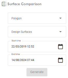
-
Select at least one polygon from the Polygon drop-down. The surface in the cross section view will be restricted to the area with the polygon.
-
(Optional) select any design surfaces to be included in the comparison.
-
Fill out the Start time and End time fields to specify the dates to show data for. Set these to the same date and time to show the surface at a single point in time, or set different dates to compare the surface between two points in time.
You can also set the Start time and End time fields by dragging the yellow arrow heads in the timeline at the bottom of the viewer.

-
Hover over the timeline and use the mouse scroll wheel to zoom the timeline in or out. Alternatively, right click on the timeline and drag the mouse left or right.
-
Set the Start time by dragging the left yellow arrowhead, or by clicking a point on the timeline to the left of the timeline centrepoint.
-
Set the End time by dragging the right yellow arrowhead, or by clicking a point on the timeline to the right of the timeline centrepoint.
-
-
Click Generate.
The view will enter surface comparison mode and controls will appear in the view.
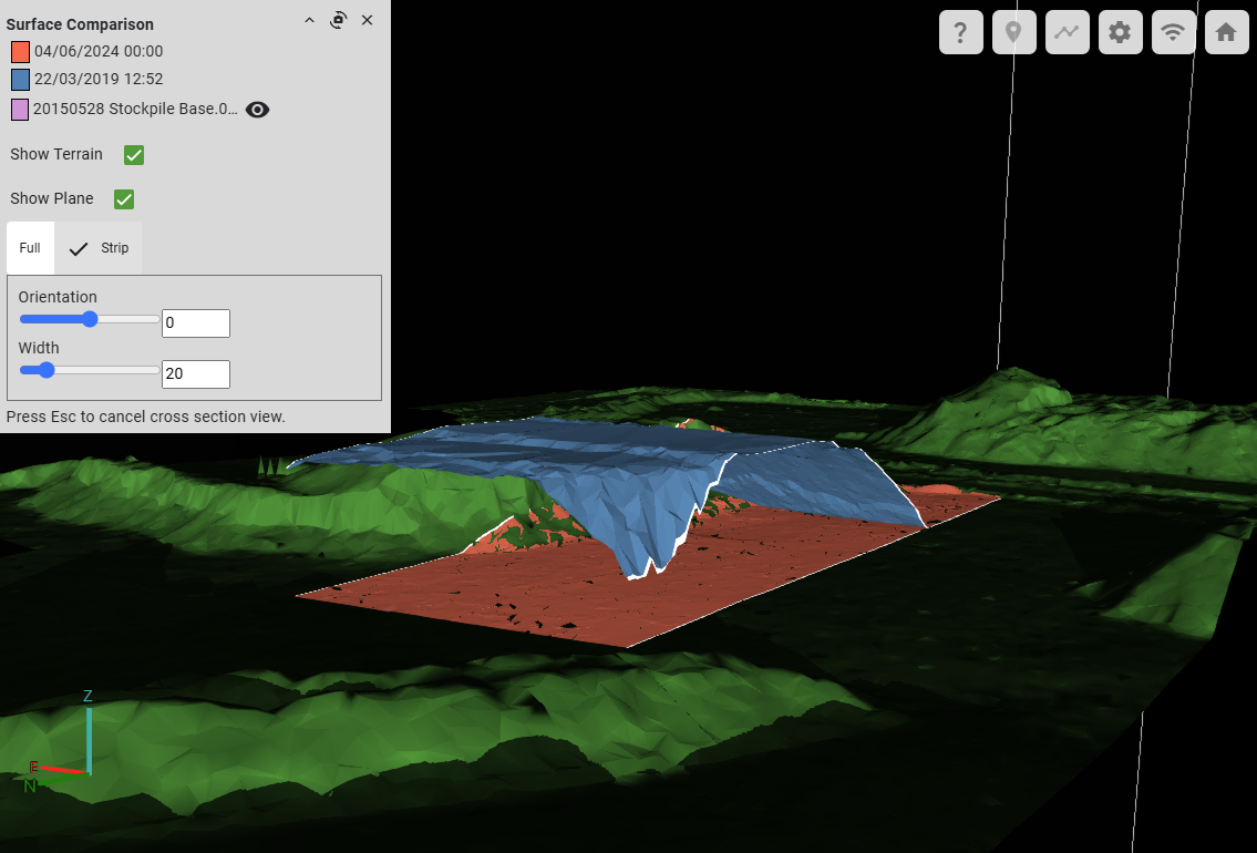
Configure the surface comparison controls as follows:


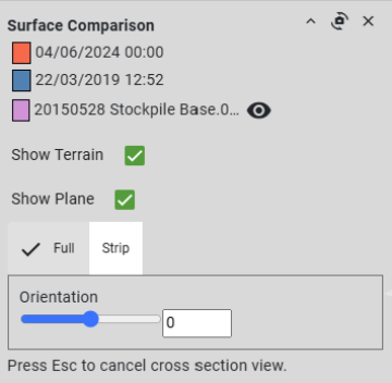
Click the colour swatch next to a surface date and time to change the base colour for that surface. Show Terrain Select to show the surface terrain outside of the selected polygon; clear the checkbox to hide the surface terrain.
Compared surfaces with terrain showing
Show Plane When selected, the cross-section plane is displayed. Cross-section planes appear as white squares around the area of interest and intersection edges with the surfaces. Deselect if you need to hide the plane. Full/Strip Select the preferred cross section view.
-
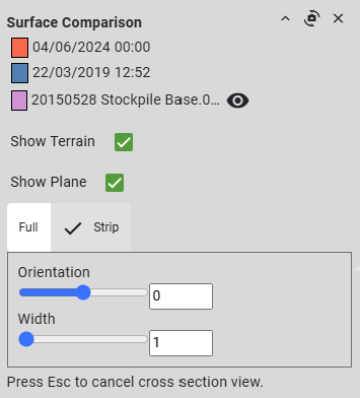
Full will display surface extents behind a single cross section plane.
-
Strip will only display the surfaces between two cross-section planes.
Orientation Move the slider or enter an angle in degrees to set the orientation of the cross section plane. The angle is an offset in the XY plane from north. Width Only available in Strip mode. Drag the slider or enter a distance to set the cross-section width.
-
Use the following controls to manipulate the view while in surface comparison mode:
-
Drag with the left mouse button while the cursor is inside a cross-section plane to move the plane.
Note: In strip mode, both planes move in unison.
-
Drag with the left mouse button while the cursor is outside the cross-section planes to move the view.
-
Drag with the right mouse button or rotate the scroll wheel to zoom the view about the cursor position.
-
Drag with the middle mouse button to rotate the view.
-
Click
 in the panel to reposition the view point perpendicular to the cross-section planes.
You can also manage the control panel view as follows:
-
Click
 to collapse the panel and see the whole viewer area.
 -
Click
 to close the surface comparison mode.
