Preparing to Use the Scanner |
This chapter describes practices and tasks to understand before using the scanner.
Carrying and placing the scanner
The scanner has handles to allow it to be lifted with either one or two hands. Follow the guidance below for each handling method.
| Handling method | Situation |
|---|---|
| One hand |
Carrying the scanner over short distances. |
| Two hands | Placing the scanner into its transit case, or removing it. |
|
Placing the scanner onto a mount, or removing it. |
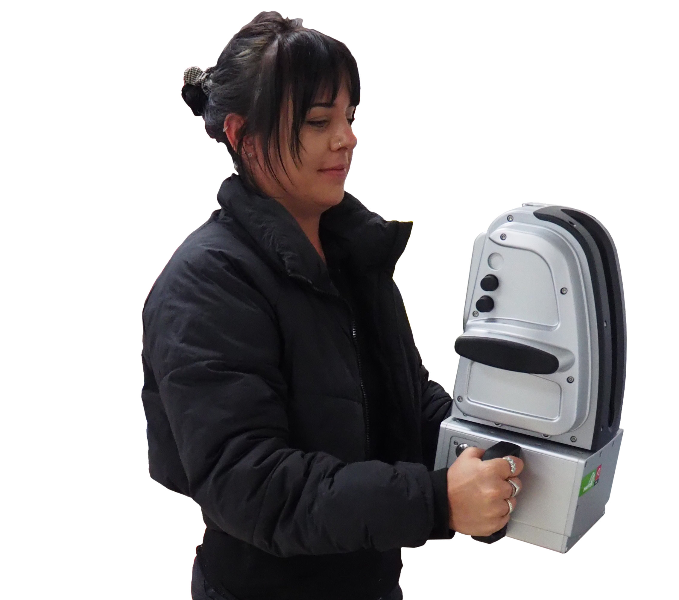
Carrying the scanner with one hand
When carrying the scanner with one hand, always use the carry handle attached to the scanner head with the scanning window facing towards your body (see Figure 4-1). Additional care should be taken with dual-window scanners to prevent accidental damage to the rear window.
Ensure the scanner is always placed down on its scanner rest. Placing the scanner in other orientations without the use of an appropriate mount could cause it to topple.


Removing or placing the scanner into its transit case
Hold the scanner by the handles on the scanner body as illustrated in Figure 4-2.
|
|
Important: Never place the scanner face up in the transit case. This may cause damage to the scanner in the event of an impact. |
Placing the scanner onto a mount
|
Important: Always hold the scanner using two hands when placing it onto a mount. |
Carrying the scanner using the transit case
The transit case includes wheels that are ideal for use on smooth surfaces. Extend the pull-handle before use, as illustrated in Figure 4-4.

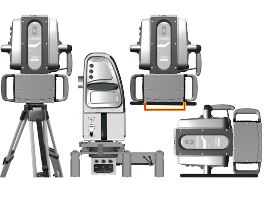
Summary of recommendations for placing a scanner
To prevent damage to the scanner, follow the recommended methods as illustrated below when mounting or placing the scanner on a surface.
|
Recommended
|
Not recommended
|
|
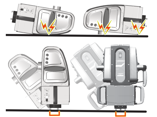
Figure 4-5 The scanner can be safely mounted on a tripod or vehicle mount, or placed sitting upright with no tribrach adapter fitted or horizontally on its resting pad. |
Figure 4-6 Never place the scanner on a surface with its front or back facing down. Do not stand the scanner on its tribrach adapter. |
Fitting scanner mounting hardware
Mounting hardware allows the scanner to be securely mounted onto a scanning platform.
Tribrach adapter
The tribrach adapter allows the scanner to fit onto a standard tribrach (part # 0101000), or the optional tribrach adapter clamp (part # 0102230).
|
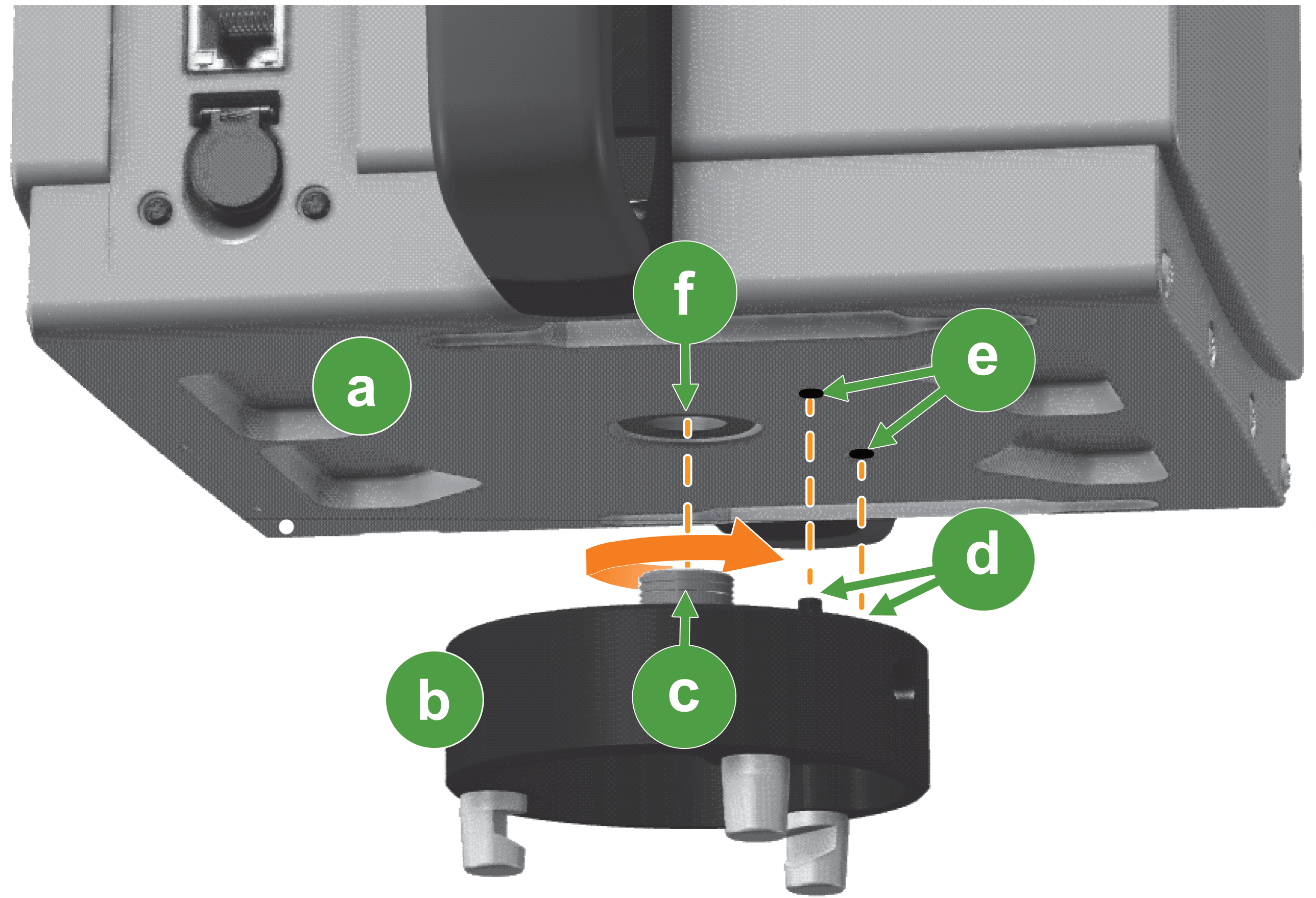
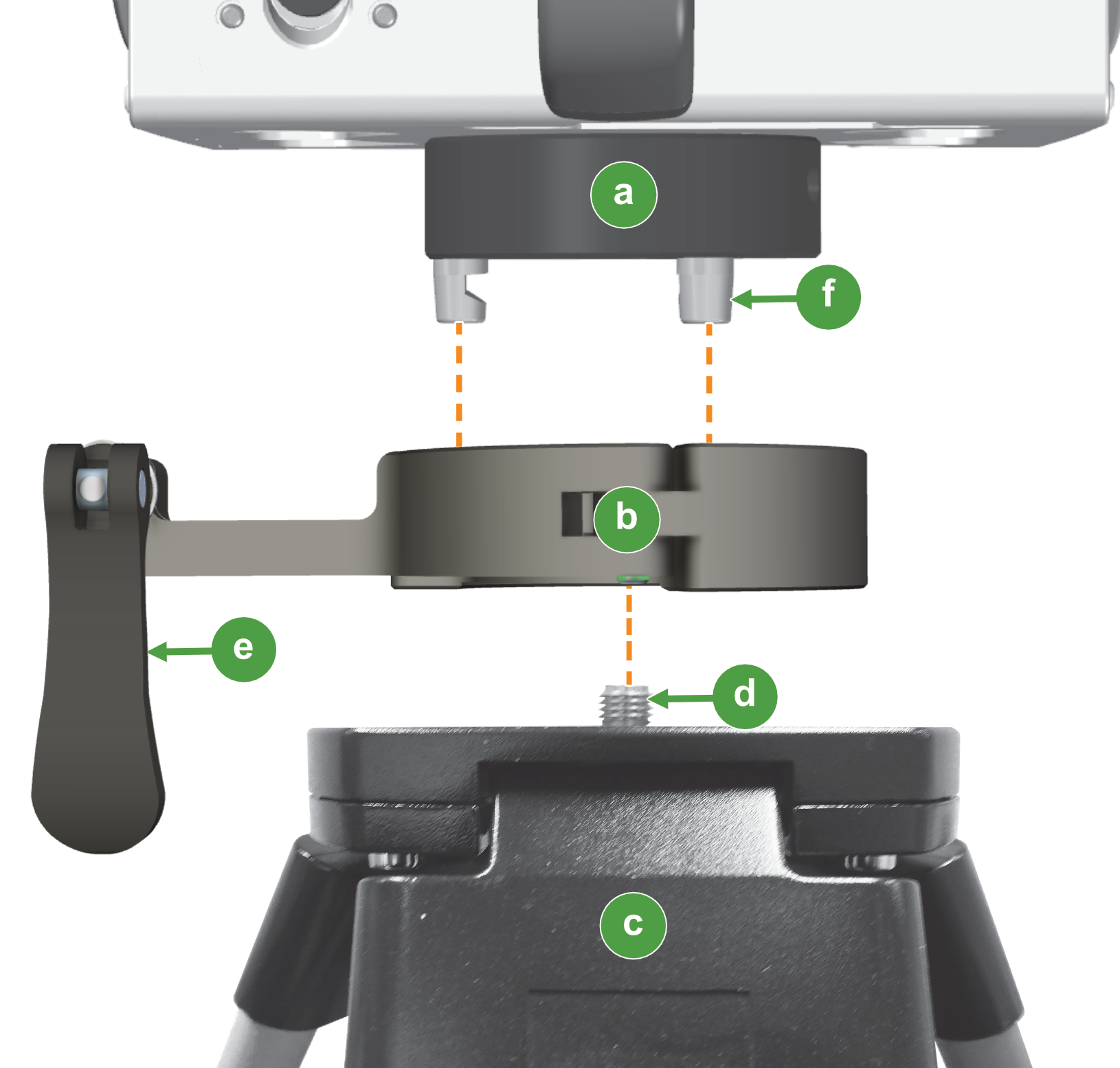
To fit the tribrach adapter, refer to Figure 4-7 and follow these steps:
-
Place the scanner in a horizontal position (sitting on the resting pad and right-hand side handle).
-
Align the flat face of the tribrach adapter so the two pins
 are oriented with the tribrach alignment sockets
  on the scanner base.
 -
Using the T-shaped hex key, turn the captive bolt
 counter-clockwise to screw it into the 5/8″ threaded hole
  on the scanner base.
 -
Check that the tribrach adapter sits flat against the scanner base, then firmly tighten the captive bolt.
-
To remove the tribrach adapter, simply unscrew the captive bolt and pull the tribrach adapter free.
Tip: The tribrach adapter can remain attached to the scanner when used with a mobile mount, and when stored in the transit case.
Scanner interface plate
The scanner interface plate (included with the Drive or Vehicle Mount kit) is an adapter that is fitted to the scanner to adapt it to the vehicle mount frame.
You must install the scanner interface plate if it is not already fitted. A field calibration must be performed before use. Factory-fitted plates are pre-calibrated.
To learn more, follow the instructions for fitting the interface plate and performing the Drive field calibration procedure in the Maptek Drive Mount R3 Series Installation Manual.
Powering the scanner
Depending on the use case, the scanner can be powered by an internal battery or using an external power source.
Inserting the scanner battery
Figure 4-8 illustrates inserting the battery into the scanner. To insert the battery, pull the door latch  and open the battery door
  . Orient the battery so its connector matches with the battery bay connector , then push the battery into place. Close the door, checking it is correctly latched shut.
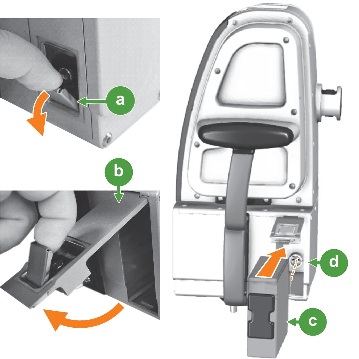
Open the latch before closing the battery door. Do not force the door closed; doing so may damage the latch mechanism.
|
Correct:
|
Incorrect:
|

Checking the scanner battery state of charge
Always recharge the Li-ion battery as soon as possible when a low state of charge is reached. To check the battery state, you can view the battery level indicator on the battery, or if connected to the scanner with the FieldHHC tablet you can check the scanner power status in the status bar.
|
|
|
|
Figure 4-9 Left: State of change indicator on the battery. Right: Scanner battery level indicator in FieldHHC. |
|
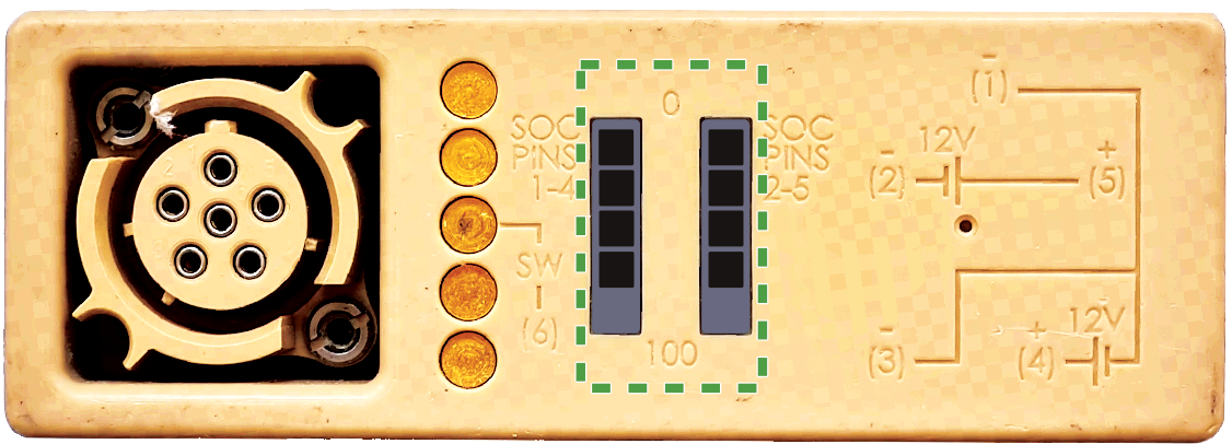

Tip: The battery indicator displays in 20% increments for each of the two internal battery sections. The FieldHHC tablet power state indicator displays the total battery level in 1% increments.
Charging the scanner battery
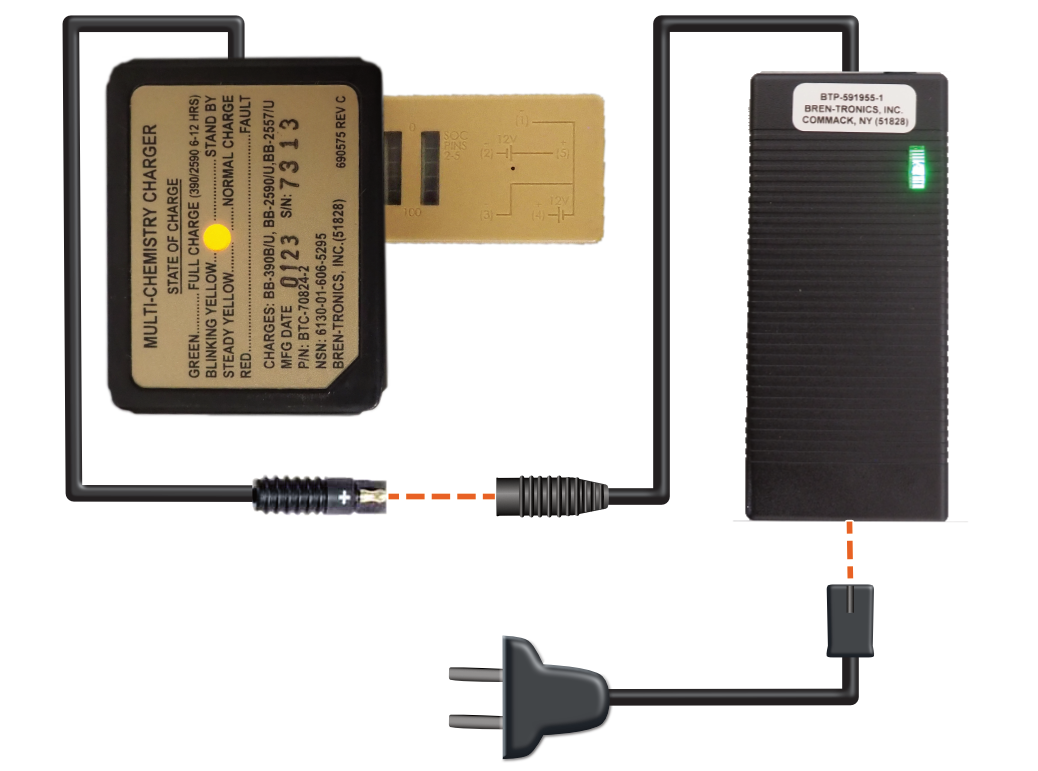
Connect the battery charger to the AC to DC power adapter, then connect the battery to the charger as illustrated in Figure 4-10.
To recharge the battery in the vehicle, use the 12 V DC car adapter supplied with your scanner charging kit.
Note: While recharging, a steady amber light is displayed on the battery charger. The light turns green when the battery is fully charged.
Connecting external power to the scanner
Connect the scanner using the 24 V DC port when using Maptek Drive, vehicle mount, or Sentry systems.
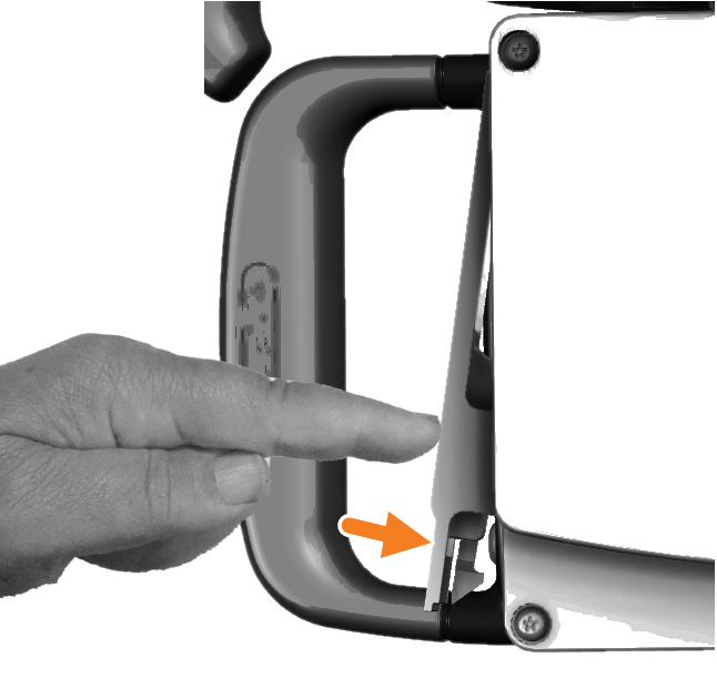
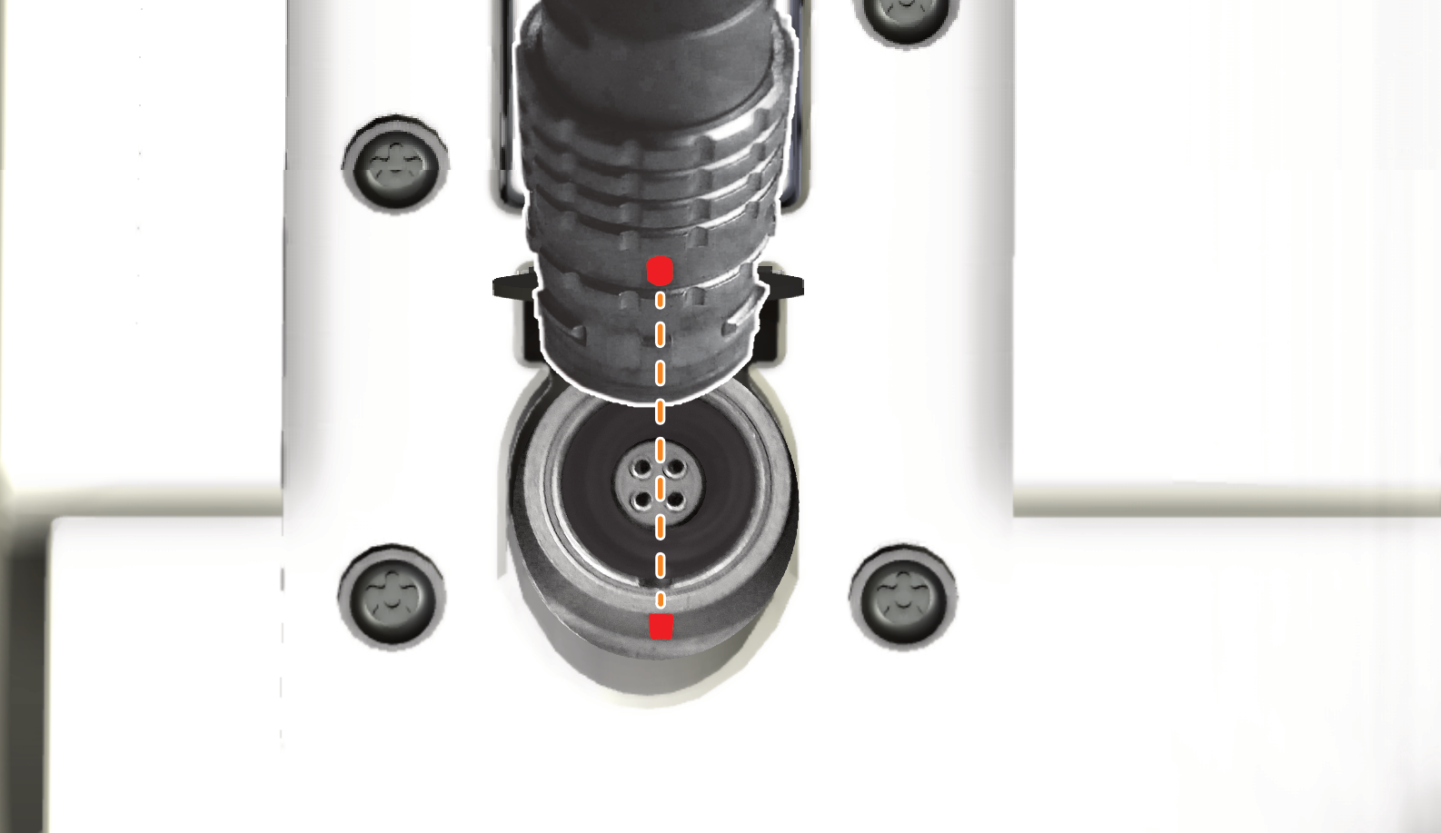
To connect the power lead to the scanner, lift the spring-loaded cap and orient the plug so that the red mark aligns with the matching mark on the socket, as illustrated in Figure 4-11.
Push the plug in until it clicks into place. To disconnect the plug, simply pull it out.
Scanning in cold conditions
Cold conditions are defined as temperatures that fall below the normal operating range of the scanner. Additional considerations apply for scanners operating at significantly lower temperatures or exposed to effects such as wind chill. Table 4-1 explains the different operating conditions in which scanners may operate.
Preparing to scan in cold climate with M20 scanners
When preparing to scan in temperatures in the limited-exposure range, the following measures are recommended:
-
Keep the scanner in the warmest possible location when not in use.
-
Keep the scanner in its transit case whenever practicable.
-
Place chemical hand warmers inside the transit case.
-
Minimise the scanner’s exposure to the elements whenever possible.
Fitting the neoprene jacket to the scanner
The neoprene jacket provides thermal insulation. Always fit the jacket to the scanner before operating in limited exposure temperatures. To fit the jacket, follow the instructions as illustrated in Figure 4-12.
|
|
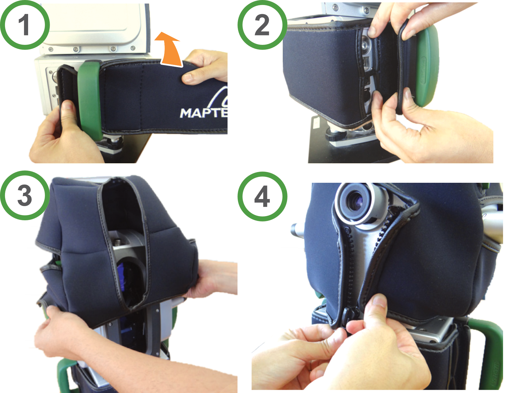
Note: Ensure that the cut-outs on the neoprene jacket align with the controls and ports on both the scanner body and scanner head. Ensure the jacket does not obstruct or interfere with the operation of the scanner head as it moves.
Important: Always fit the neoprene jacket when expecting cold to very cold conditions. Failure to do so could result in the scanner ceasing to operate or developing a fault, requiring repair. If the scanner is too cold to operate, the cold-climate indicator  in the FieldHHC status bar will turn red (M20 only). An error message will display and be recorded in the log file.
-
Remove the neoprene jacket before placing the scanner into its transit case.
-
Where possible, use external power when operating in cold climates. Battery life is reduced in very cold weather.
-
The neoprene jacket is not required when operating in warmer climates and can be removed when cold climate conditions are not expected.
Recovering a cold-soaked scanner
A scanner that has been exposed to cold temperatures to the extent of malfunctioning is considered cold soaked. To recover from this condition, immediately do the following:
-
Stop scanning and power the scanner off.
Important: If the scanner head does not return to its at-rest position, do not manually rotate the scanner head—this may damage the scanner, requiring repair.
-
Remove the scanner from the cold exposure environment. Keep the scanner in a protected environment and allow time for the scanner to warm up to ambient temperature—ideally, this should be at 20°C (68°F) or greater.
Attaching a GPS device to the scanner
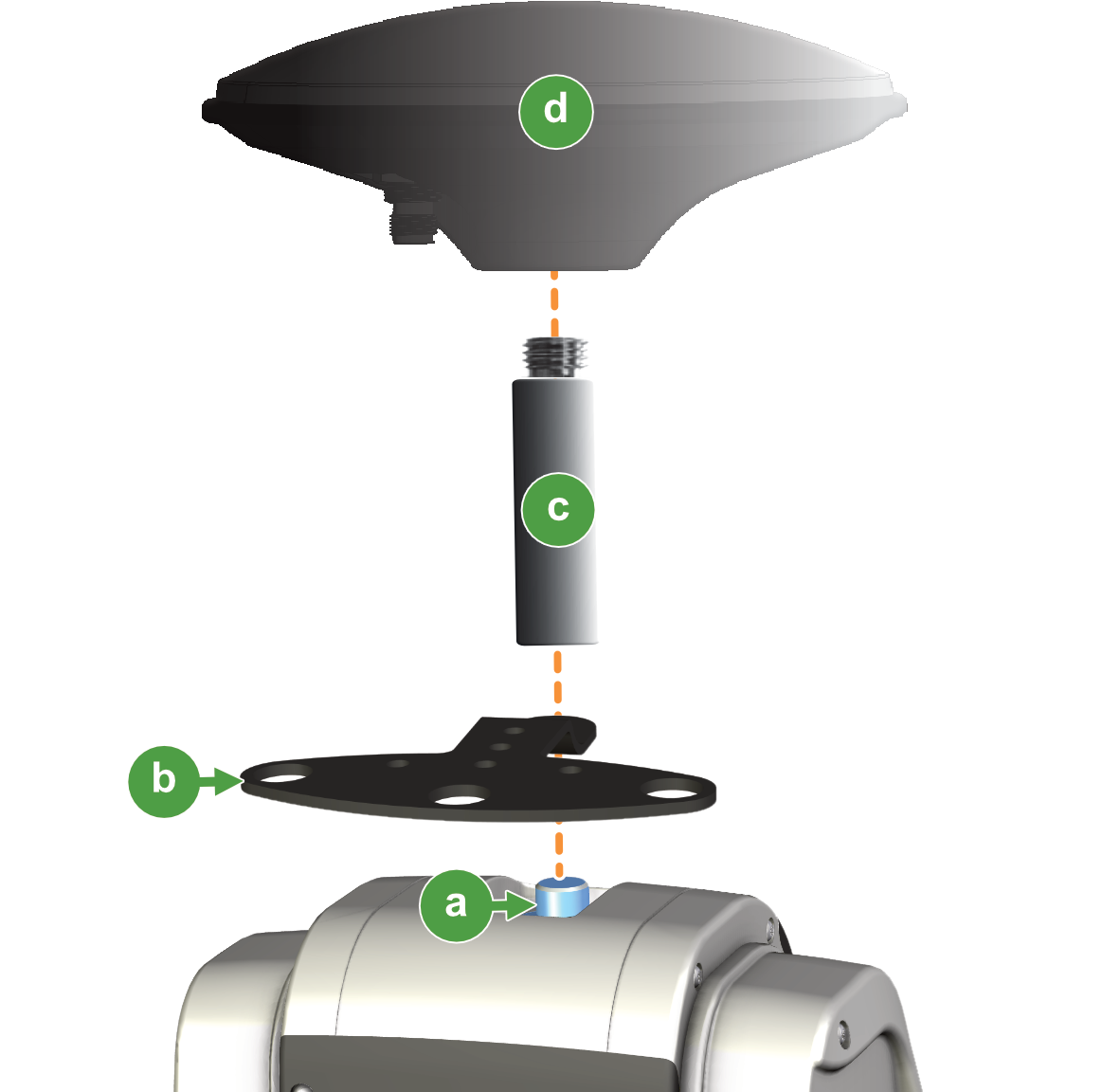
The GPS antenna or rover should be attached to the GPS threaded adapter on the scanner. Maptek recommends using a spacer fitted to the GPS threaded adapter, as illustrated in Figure 4-13.
|
Mounting the scanner to a tripod
To fit the scanner to a surveyor’s tripod, first attach the tribrach adapter by winding the 5/8″ mounting screw into the base of the tribrach. The procedure is the same if using the clamping plate. See Figure 4-14 and Figure 4-15 respectively.
|
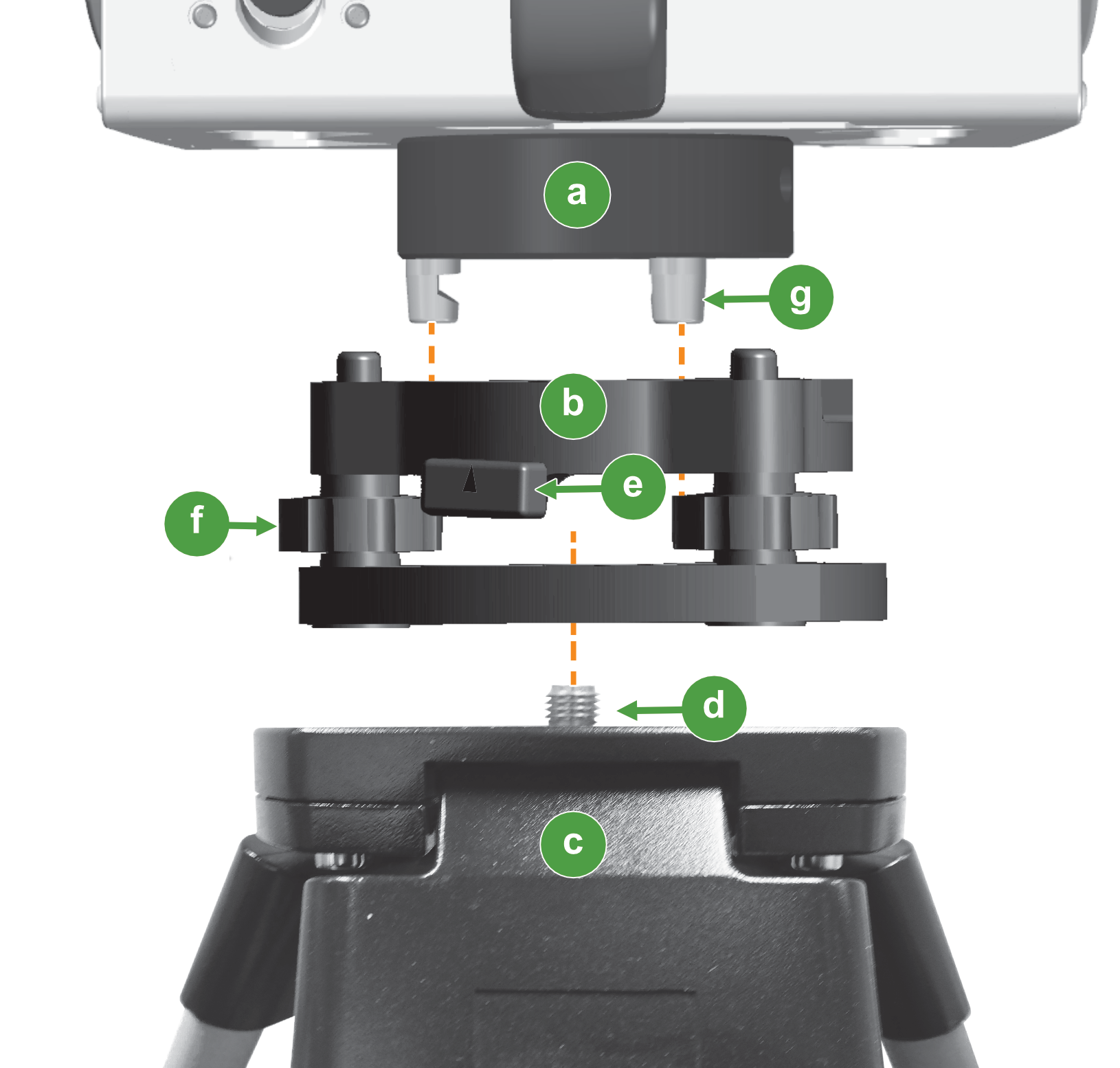

Note: Ensure the tribrach locking lever is open before placing the scanner on to the tribrach. Ensure the tribrach pegs are located through the holes in the tribrach.
|
Note: Open the tribrach clamp before placing the scanner onto the tribrach clamp. Ensure the tribrach pegs are located through the holes in the tribrach clamp.
Note: For detailed mounting instructions, refer to the Maptek Drive Vehicle Mount R3 Series Installation Manual, supplied with the Maptek Drive or Vehicle Mount kit.
Enabling or disabling Wi-Fi on the scanner
The onboard Wi-Fi module is normally enabled so you can conveniently connect to it with the FieldHHC tablet or a mobile device. Where circumstances do not permit its use, it can be disabled, following these steps:
-
If the scanner is on, press the power button to turn it off.
-
Press the power button to turn the scanner on. When the power button starts blinking, press and hold the power button.
-
Release the power button when the scanner head starts to starts to move. Wi-Fi is now disabled on the scanner.
-
To enable Wi-Fi, repeat steps 1–3.
-
To check the Wi-Fi state, switch the scanner off then on and observe the blinking light on the power button as the scanner starts. If the last blinks are red, Wi-Fi is disabled. If the last blinks are green, Wi-Fi is enabled.
