 Site Configuration Options
The site configuration menu allows administrators to configure the system-wide behaviour of MaterialMRT, from system attributes to various metrics and other global properties.
Site Parameters
This page allows you to adjust the attributes of the mine and the behaviour of its materials, as follows:
| Global |
Cuboid Length and Width: A cuboid is a block used for modelling stockpiles. It is similar to a conventional block-model block, except that its height varies by the quantity of material within the cuboid base. To set the length and width of the cuboid, enter its value in this field. Note: Cuboid length and width can only be changed if no materials have yet been modelled in the system. |
|
Typical Material Density |
The typical material density can be set in this section. Typical materials can be categorised as non-specific material such as waste or run-of-mine (ROM) material. In here, you can do the following:
|
|
Zone Category |
Zone categories allow you to determine whether a zone has a static or dynamic boundary. Use the checkboxes to enable or disable static boundaries. |
|
Rule |
Rules are scripts (TypeScript) used to validate data associated with the movement of material. Choose which rules are enabled for MaterialMRT to use. Grey checkboxes indicate mandatory rules. |
|
The cuboid stack modeller adjusts the behaviour of material that is added or removed from a stockpile. The settings are as follows: Note: Changing these settings may affect system performance.
|
|
|
Stockpile Boundary Modeller |
The stockpile boundary modeller allows you to adjust the vertical modelling behaviour around a stockpile. The settings are as follows:
|
|
Domain Event Dispatcher |
The domain event dispatcher allows you to set the threshold of the number of events logged before they are dispatched to the system, and the lag time before a replay is triggered. The settings are as follows:
To change the values for H, M, and S (hours, minutes, and seconds), you can enter the value directly into each field, or use the |
|
Stockpiling |
Stockpiling allows you to set the age waste dump material reaches before being archived. Select any of the following:
|
Preferences
This page allows an administrator to define the technical and operational characteristics of the mine site. Click on a preference category on the side bar to view and edit its settings, as follows:
|
Site Metadata |
Site metadata identifies the MaterialMRT website instance, and can synchronise schedules with Evolution Epoch. The settings in this tab include the following:
|
|
CRS and Local Transformations |
Control how your terrain coordinate data is mapped. The parameters are as follows:
|
|
Units |
Set standard units for all metrics. Click the drop-down arrow to expand and choose the required unit of measure. |
|
Stockpile Status |
Choose the colour for undefined materials using the colour picker. |
|
Cesium Default Viewer Assets |
Add or remove viewer terrain (assets). Click
|
|
Zone Categories |
Review and manage the zone categories that are listed in this panel. Information is divided into the following columns:
|
|
Enter your language and regional settings in this tab. The following fields apply:
Tip: For each of the above, begin typing a keyword to narrow the search. For example, if you type “US” into the Culture field, matches such as chr-US, en-US appear. You can do the same to find the correct Time Zone. Alternatively, open the entire list by clicking in any of these fields while it is blank. |
|
|
Shift Calendars |
Select the shift regime used at the site. Use the drop-down list and select the appropriate shift calendar. A shift schedule includes the Name (such as night shift), the Start, and End time of each shift. |
|
Viewer |
Use Viewer to control the amount of padding around the extents of all the combined zones. The unpadded extents will be a rectangle that is sized to fit the outermost extents of zones within the terrain. To best see this effect, configure any viewer using the following settings:
Tip: To learn how to configure a viewer, see Getting Started > In-viewer configuration controls. Example
The following example shows the white boundary conforming to the yellow zone boundaries when they have no padding.
To set padding uniformly, do the following:
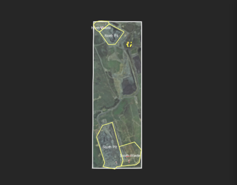
Example
The padding between the yellow zone borders and the white extents border. In this example, the padding value is 200 m. 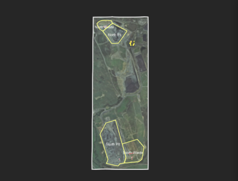
You can also define explicit minimum and maximum x- and y-axis (mine grid) coordinates, as follows:
Example
Note the padding effect (particularly the vertical extents when custom settings are applied:
To save your settings, click |
| Built-in Metric Colouring |
Manage the colour schemes for the following metrics. The following default metrics are available:
Metrics can also be customised as needed.
|

 to open the customise colour map editor to modify an existing colour map assigned to a metric.
 button to choose a pre-made colour map and customise it.
Material Properties
The Material Properties Schema contains the list of properties with its related values presented as a table, and the property editor, as illustrated. The table includes the property name, its type, and sources referenced with each property.
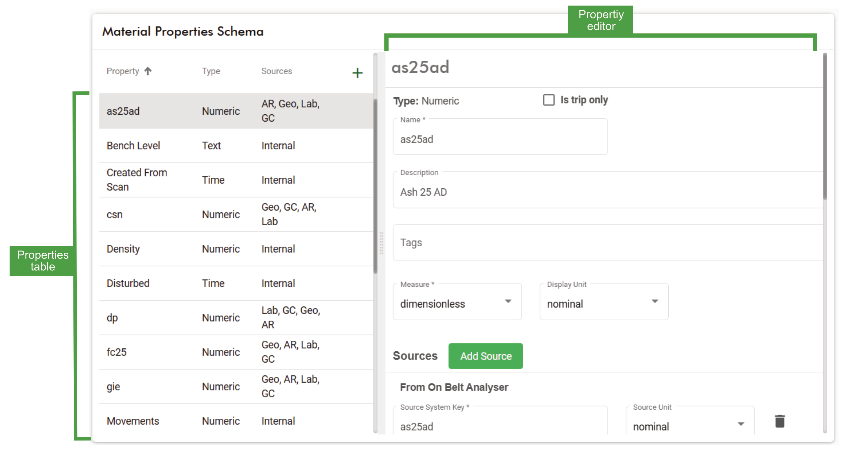
You can add new properties or select an existing property to modify or delete from the material properties schema.
Adding a new material property
To add a property, click ![]() at the top-right corner of the list pane. A new form; New Material Property will open in the property editor. Enter the following information by following these steps:
at the top-right corner of the list pane. A new form; New Material Property will open in the property editor. Enter the following information by following these steps:
Note: Fields marked with an asterisk (*) are mandatory.
-
Open the Type drop-down to select from the available options. To learn more about property types, refer to the Property types table.
-
Select the Is trip only checkbox if the property is not intended to carry through to cuboid stacks, stockpiles, or outflows. The information is only retained in the trip and can be used in downstream reporting systems.
-
In the Name field, enter the property’s name.
-
In the Description field enter a description for this property, if required.
-
Click in the Tags field to add or select an existing descriptor, if required.
-
Open the Measure drop-down and select the appropriate metric.
-
Open the Display Unit drop-down and select the appropriate unit, if required.
-
In the Sources section, click
 to open the drop-down and select a source. Repeat this step as required to add more sources.
 -
Under each source (From FMS, etc), enter the Source System Key as named by the source.
ExampleDifferent sources may have different naming variants from the source system key such as a7, a-7, or ash7 etc.
Note: To correctly map a property to its source system, ensure the source system key exactly matches the source name
-
In the Value Ranges section, click the
 icon to enter the Acceptable, Marginal, and Unacceptable value ranges. Repeat this step to include additional value ranges as required.
 -
In the Colour Map section, add a colour map to use as the legend, if one is required. Click
 to open the Customise Colour Map editor. Here, you can select your colours, value increments, and visual styles.
 Alternatively, click
 to open a list of pre-made colour maps. Select one to use and modify as required. Click
  to save.
-
Click
 to save the created property.
Managing existing properties
To remove a property from Material Properties Schema, follow these steps:
-
Select the property from the list
-
On the editor pane, scroll down to and click
 . A confirmation dialog will open with the following warning, as illustrated.
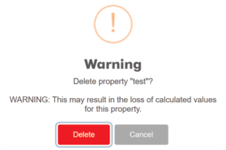
-
Click
to confirm your choice. The selected property will be removed from the list.
To modify an existing property, follow these steps:
-
Select the property from the list.
-
In the property editor, select the attribute to modify or delete
- Enter or edit attribute values as needed.
- Click
 next to an attribute you want to delete.
-
Click
 to save your changes.
Resource Model Explorer
The Resource Model Explorer is an administrative tool that displays and lists grade control and geological block models. The page includes a viewer to display block models and three tabs that allow you to explore, import, and manage models. To open the resource model explorer click  in the system bar and select
  .
.
Viewing blocks and their properties
The viewer displays the following features, depending on the type of block model selected, as follows:
-
Grade control models are within an area surrounded by a cyan border. The blocks appear at the level of the terrain, as illustrated. They are displayed in the colour scheme of the selected property.
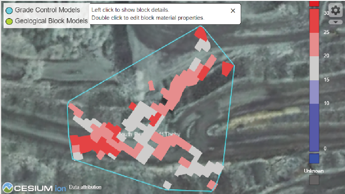
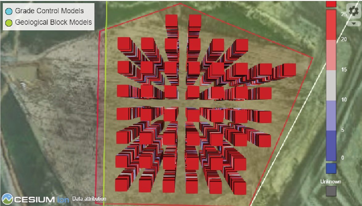
-
Geological blocks are within an area surrounded by a light green border. They appear as stacked blocks below the level of the terrain, as illustrated. Geological blocks are also displayed in the colour scheme of the preferred property.
 Note
NoteTo show geological blocks after selecting a model from the Property value drop-down, click
 and create a polygon over the area you want to select, then click
  . Geological blocks within the polygon will be displayed, and their details listed in the adjacent table. The blocks are defined by their Block ID, Centroid (position), Size, and Properties.
-
Click on a block in the viewer to locate it in the table. The opposite can be done; however, it may be difficult to locate blocks if they are obscured by others.
-
Click the centroid pin (
 ) to open a separate viewer page showing the location of the pin.
-
-
Use the viewer to find information about any block.
-
Adjust the viewing angle to locate and select a block with the mouse, particularly for geological blocks that can contain many stacked layers. The selected block will be highlighted in the resource model's table when the Editor tab is selected.
-
Expand the Property value drop-down to display blocks in the colour scheme of that property.
-
For grade control blocks, apply bandpass filtering by adjusting the Min and Max fields. Blocks outside the bandpass range will not be displayed. See the following examples for comparison:
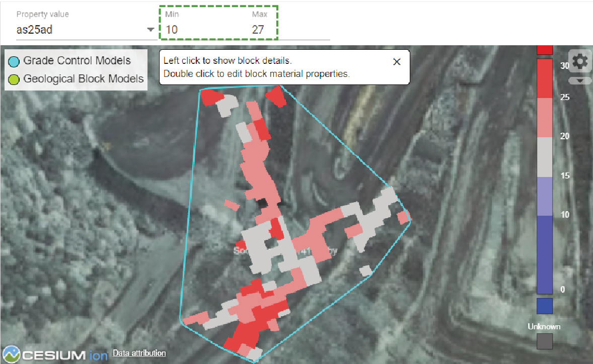
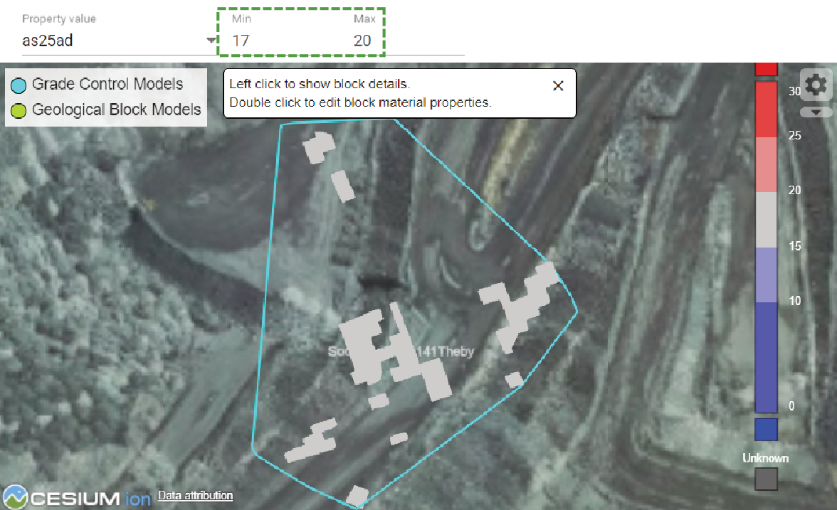
-
Click on a block to view a statistical tooltip. As soon as you move the mouse away, the tooltip will disappear.
-
Using the Explore tab
The Explore tab allows you to review listed block contents and quickly query their contents. When exploring grade control blocks, additional tools are available. Select a model, using the Resource Models drop-down. The way blocks are displayed depends on the type selected, as follows:
-
The viewer will display the blocks framed within a cyan boundary if grade control blocks are selected.
-
The viewer will not display any blocks initially, only a green-bordered area that indicates where geological blocks can be queried.
Once a resource model has been selected, a table containing all the blocks and their statistics will be populated in the Explore tab.
-
For grade control blocks, use the Search Name field if you want to filter down items or find a specific one.
-
Hover over a specific row in the table to find that block in the viewer. Conversely, click on a block in the viewer to find it in the table.
-
Hover over an item in the Properties column in the table to display a tooltip listing the properties in the block and their amounts.
-
Click
 (Edit properties) to open the properties editor to modify the attributes of selected grade control blocks.
  Click to see the tasks you can perform.
-
Click
 to add the next available property in the category of choice. The property will be added to the bottom of the list. If the added property is not the one you want, use the drop-down to select the correct one. Enter a value for the properties that you add.
 -
Click
 to remove a property listed in the editor. It will be removed immediately.
 -
Update the Value field of a given property.
-
-
Click
 (Delete) to remove a block from the table, when prompted to confirm the action, click .
Using the Import tab
The Import tab has tools to enable you to import geological or grade control blocks. Geological blocks are contained within CSV or ZIP files. Grade control files require a CSV file with accompanying DXF or OBJ blocks, and the filenames of both must be identical.
To import the block models, follow these steps:
-
Click
 to open its form.
 -
In the Model Name text field, type in a name for the model.
-
Open the Type drop-down and select the type of model to import.
-
Complete the remaining fields for Owner, Version, and Priority.
-
Optionally, enable the Is Active checkbox for the model to be included in typescript queries that call for models flagged as active.
-
Select the files to import:
- Click inside the drop-zone to open a file manager instance and select files.
- Drop files directly into the drop-zone.
-
Click
 to remove unwanted files in the drop-zone.
 -
Click
 to clear all files from the drop-zone.
Or
Imported files will appear as tiles in the drop-zone.
-
To finalise the import, click
 .
.
Using the Manage tab
The Manage tab consists of a table listing models currently in the system. It includes columns for the requested attributes when adding new models, namely Type, Owner, Version, Priority, and Active. The Item Count column indicates the quantity of blocks.
-
Change values in any column, except Type and Item Count by entering a new value into that cell. To save your changes, click
 .
. -
Click
to enable editing a model's attributes. -
Use the checkbox to decide which models should be active. If the state is changed, click
to save it. Note: When a model is not flagged as active it will be excluded from queries (such as certain typescript rules) that specify active models.
-
Delete a model (and its associated blocks). Click
, when the confirmation dialog appears, click  .
.
Rules Editor
The rules editor allows the creation and management of typescripts. The typescripts used are called rules which enable the use of automations to perform data queries, evaluations, and validations based on specific system or material properties. To open the Rules Editor page, click to open the menu, then select 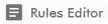 .
.
The Rules editor is arranged as illustrated below.
Selecting a rule to edit
MaterialMRT includes the following standard rules:
|
Trip Validation |
The rule is run when viewing trips on the Trip Editor page. This script performs the following functions:
If trips return error or warning validation results, the applicable column is coloured in red or orange respectively. |
|
Payload Auto Correction |
This script applies this rule to all selected trips in the trip editor. It automatically corrects the payload mass to the expected payload mass of the named truck. If the truck name does not match, an error is returned to indicate the payload mass can’t be corrected automatically. |
|
Trip Auto Correction |
This rule is run every time a truck trip is processed. It is able to modify any value available on the HaulTruckTrip model used by the rule. It also has access to various application program interface (API) methods to query related zones, stockpiles, and block models. |
|
Resource Model Property Setter |
This rule is run by the engine every time a truck trip is processed. This rule is used when selecting a grade control or geological model block to associate with a load event of a truck. |
|
Dump Location Validation |
This rule is associated with the Tip Status material property. It is run every time a trip is processed and determines if the material was deposited in the correct location. |
Editing scripts
The following steps are recommended when you edit typescript:
-
Make the required changes to your script.
-
Test your script in the Testing panel.
Note: An error message will be displayed if an attempt to save the script is carried out before testing.
Click here to view instructions for testing a typescript.
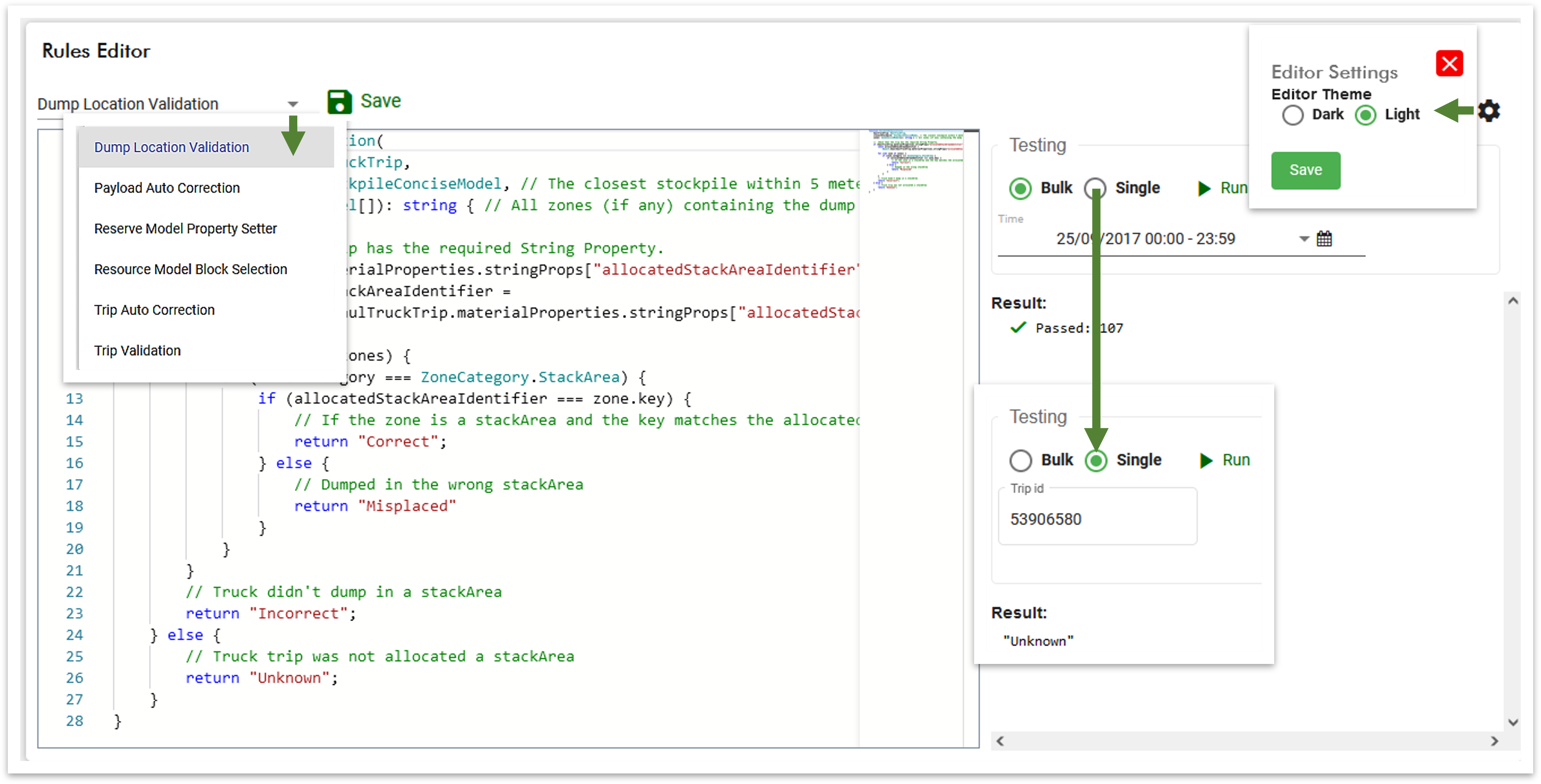
Testing your script is mandatory, as it prevents possible widespread errors from infiltrating the system. To run your test, do the following after making changes to a script:
- Decide whether to run a bulk or single iteration by selecting the Bulk or Single radio button. A bulk test runs the script from a selected date range or shift. A single test is applied to a particular trip or instance.
- Follow the step for the selected test type:
- If you are performing a bulk test, open the calendar picker (
 ) and select a custom time range.
 - If you are performing a single instance test, enter the Trip ID in its text box.
- If you are performing a bulk test, open the calendar picker (
- Click
 to execute the test. The results are displayed in the report window. An example is shown below.
 - Click
 to save your script.
-
When the script is successfully validated, click
.
Tip: To use a dark or light theme for the editor, click ![]() ( Editor Settings) and use the radio buttons to select either scheme.
( Editor Settings) and use the radio buttons to select either scheme.
Zone Maintenance
Zone Maintenance allows you to manage and import zones derived from a kml, json, or dxf file. To open the zone maintenance page, expand the site configuration menu (![]() ) and select
) and select  . The page is arranged with a tabbed panel that enables you to manage and import zones, and the viewer to display these zones over the terrain.
Managing zones
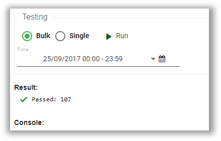
The Manage tab works interactively with the viewer. Select the Manage tab to view the table which is organised by the (zone) Name and Category.
-
Click on a listed zone in the table to select it. Additional information will be displayed in the adjacent editable panel. The zone will be highlighted and centred in the viewer. The equivalent is also true if you click on an unselected zone inside the viewer.
To show stockpile boundaries in the viewer, enable the Show Stockpile Boundaries toggle.

-
Enter a keyword in the Search Name text field to find specific zones or subsets sharing similar names.
-
Change the sort order of either column by clicking on its header.
-
Add new zones using the polygon tool and manually entering the required values.
Click here to view instructions for creating a zone.
To create a new zone, follow these steps:
-
From the manage tab, click
 to open a blank form in the zone editor.
 -
Enter the requested values. These vary by category, as follows:
Zone Name
A unique or site-derived name given to a zone.
Category
Open the Category drop-down to make a selection. A category defines the purpose of that zone. Available categories are derived from those created in the Zone Category section as explained in Site Configuration Options > Site Parameters.
Capacity
Enter the tonnage of the stockpile.
File units Open the drop-down to select an alternate file unit to apply. Conveyor speed Enter a value for the rate at which the conveyor belt moves, if applicable.
Flow rate Enter a value that a given mass of material moves past a set point every second, if applicable. Distance to analyser Enter a value for the distance the material has to travel to arrive at the analyser, if applicable. Distance to lab sampler Enter a value for the distance the material has to travel to arrive at the lab sampler, if applicable. Prefer ground scan z-coordinates
Enable the checkbox to use terrain scan elevation over the imported scan, where possible. -
Click
 (add polygon) and begin plotting the area in the viewer. Alternatively, import a polygon by dropping a
 KML,JSON, orDXFfile into the drop-zone. -
Click
 to save the zone. The new zone will be displayed in the viewer.
 Tip: You can adjust or reposition a zone as required. Select the zone you want to edit then click
 . Follow the same actions used for editing any polygon (see Getting Started > Modifying polygons to learn more). After you finish editing, click to save your changes.
 -
Click
 beneath the zone editor to finalise the newly created zone and add it to the Zones list.
-
- Delete obsolete zones. Select the unwanted zone from the table, then click . A warning dialog will appear to confirm your request.
Importing zones
The Import tab enables you to import zones in bulk. You can select any combination of KML, JSON, or DXF files and drop them directly into the drop-zone, or click on it to navigate to your source files. The steps involved are as follows:
-
From the File Units drop-down, select the preferred unit to apply to the zones to be imported, if required.
-
Select Prefer terrain scan z-coordinates to use them instead the existing zone elevation data (if included with the source files).
-
Choose the following ways to import a file (supported file types are KML, JSON, and DXF.):
-
Drag a file into the drop-zone below the zone editor.
or
-
Click in the drop-zone to open an explorer box and navigate to your source.
The added files will appear as tiles in the drop-zone and be added to a table below it.
-
Click
in any tile in the drop-zone to remove it. It will also be removed from the table. -
Click
 to remove all files from the drop-zone and table.
-
-
Use the check boxes to select which zones to include, by default, all zones will be selected.
Tip: If you have many zones in your list, consider using Search Zones to filter the list.
-
In the Category column, allocate a zone category using the drop-down. All zones must have a zone category allocated to it.
-
In the Capacity column, enter the capacity (tonnage) expected to be in each zone.
-
Click
 to complete the import.
To view the newly imported files, select the Manage tab.
Exporting all Zones
You can export all zones to a file in the units of measure you have set. Simply click the  button and select your preferred file format (KML, JSON, or DXF) from the drop-down. A file is created with no further prompt and saved in your default download directory as
 <Site Code>.zones.xxx.
The following is exported as a JSON file DEMO.zones.json
where:
-
DEMOis the site code. -
.zonesidentifies this file as zone data. -
.json is the output format selected by the user.
