Dimension Line
Source file: dimension-line.htm
Dimension
lines can be created to annotate dimensions in the view
window.
-
On the Create ribbon tab, go to the Create group. From the Annotation drop-down list select
 Dimension
line.
Dimension
line.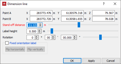
-
Enter the location for Point A (point to measure from), or click the starting point in the view window.
-
Enter the location for Point B (point to measure to), or click the end point in the view window.
Tip: You can use the action plane to assist in placing the dimension lines. Set the action plane then the text and offset of the dimension line will be drawn as close to the orientation of the action plane as the measurement "A" and "B" points allow.
Note: If using the mouse, the dimension line, text and stand-off distance are drawn dynamically while dragging the mouse, so you can see how it will be rendered.
You can still follow the remaining steps if you wish to make further manual adjustments. -
Specify the Label height.
-
Choose whether to use a Fixed orientation label. If so, you can adjust the fixed position by clicking Flip horizontally and or Flip vertically. If fixed orientation is not selected, the label will automatically adjust orientation to remain readable as the view is changed.
-
Specify the Stand-off distance: The distance between the dimension label and the measurement location.
-
Click OK or Apply to complete.
The
dimension line is created and stored in the cad![]() container by default and is displayed in the active view window.
container by default and is displayed in the active view window.
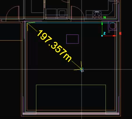
The dimension line and text are drawn dynamically while dragging the mouse.
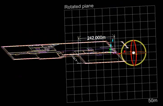
The dimension line can be oriented using the action plane.
