Blind Zone
Source file: blind-zone.htm
A blind
zone  on a stereonet represents
the region of trend and plunge of discontinuity poles that
are perpendicular to those of drillholes used
to take samples i.e. the discontinuities line
up or are approximately parallel
with the drillhole. This region
is of interest because any potential discontinuities that line
up with the drillhole are likely to be missed as they don't pass
through (or intersect). Hence it
is possible
there will be many discontinuities around
the drillhole but no samples in
the drillhole.
on a stereonet represents
the region of trend and plunge of discontinuity poles that
are perpendicular to those of drillholes used
to take samples i.e. the discontinuities line
up or are approximately parallel
with the drillhole. This region
is of interest because any potential discontinuities that line
up with the drillhole are likely to be missed as they don't pass
through (or intersect). Hence it
is possible
there will be many discontinuities around
the drillhole but no samples in
the drillhole.
-
This tool defines a stereonet region of an unknown quantity of discontinuities. There can be none, some or many.
-
Prior to creating great circles, a stereonet must be created.
-
Open the Stereonet intended to show the blind zone.
-
On the Geotechnical ribbon tab, go to the Stereonet group and select
Blind Zone. -
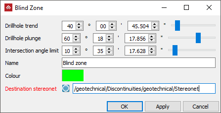
Enter the following values into the fields on the Blind Zone panel:
- Drillhole trend: angle from North (see Glossary).
- Drillhole plunge: angle down from horizontal (see Glossary).
- Intersection angle limit: the angle around the drillhole trend and plunge within which discontinuities are included in the blind zone.
- Other information such as a Name, Colour (for the lines surrounding the zone) and Destination stereonet.
-
Select OK or Apply to create lines defining the blind zone limits on the stereonet specified in the Destination stereonet container.
Example of the region or band
of trend and plunge representing a blind zone for a drillhole.
(drillhole trend = 40°, drillhole plunge = 60°, Intersection angle limit = 10°
)
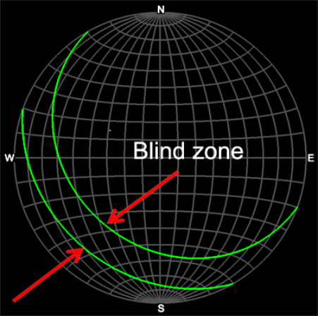
The results are graphically illustrated in the view window.
