Action Plane
Source file: action-plane-group.htm

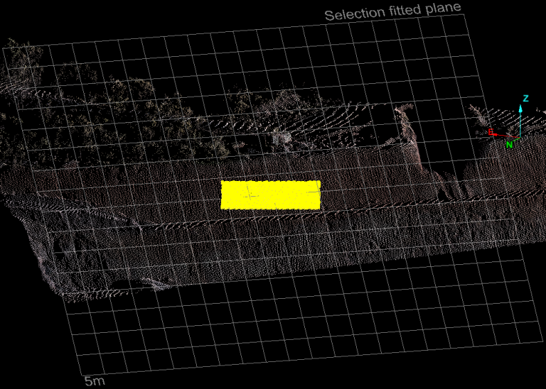
The action plane provides a mechanism to help place points in 3D space as well as set up a convenient 2D plane to perform 2D functions on. The action plane can be widely manipulated and placed around a scene, floating in space at different angles or fixed to strategic reference points on a surface.
The action plane's appearance can be adjusted in PointModeller preferences on the View window > General tab.
Some of the functions that operate directly on the action plane include:
- 2D line
- 2D polygon
- Circle
- Rectangle
- Offset line
Other functions benefit from the placement and adjustment of the action plane, especially when used with the snap modes.
The action plane tool group, found on both the view window tool bar and the View ribbon tab, provides many functions related to the action plane. These include:
- Setting action plane position—several options for defining the position of the action plane using points and planes.
- Moving action plane— several options to translate and rotate the action plane.
- Saving and restoring action plane—save action plane locations for easy future referencing.
- Toggling action plane visibility—hide or show the action plane.
- Toggling action plane manipulator—hide or show the action plane manipulator. A widget allowing the user to manually translate and rotate the action plane from any chosen point on the action plane.
- Choosing predefined views—choose between standard orthogonal views around the action plane's axes.
- Viewing Sections—special mode for viewing strips parallel to the action plane.
| Icon | Description | Shortcut |
|---|---|---|
|
|
Set action plane position |
N/A |
|
|
Toggle action plane visibility |
Shift+A |
|
|
Toggle hide or display action plane manipulator |
Shift+C |
|
|
Choose predefined views |
N/A |
|
|
Step forwards or backwards through saved action planes | Shift+B / Shift+F |
|
|
Save and restore action plane |
N/A |
|
|
Quick Section action plane |
N/A |
|
|
Section view mode |
/ (toggle ) |
| Section Manager | Shift + / | |
|
|
XY Slice (located in Position and Filter > View) |
N/A |
Setting an action plane
Use these commands to set the position of the action plane using various reference points or planes.
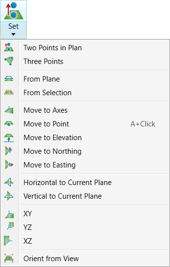
On the
View ribbon tab, go to the Action Plane group. From the ![]() Set drop-down list select one of the action plane options.
Set drop-down list select one of the action plane options.
Move action plane
Use these commands to move the action plane to a new position.
On the
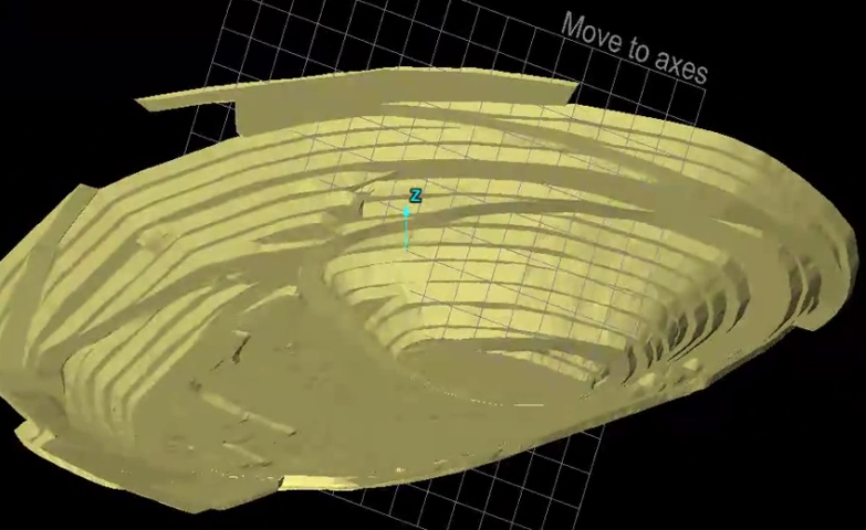
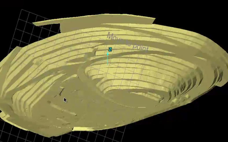
View ribbon tab, go to the Action Plane group. From the ![]() Set drop-down list select one of the Move to actions, then click in the view window to set the new position for the action plane.
Set drop-down list select one of the Move to actions, then click in the view window to set the new position for the action plane.
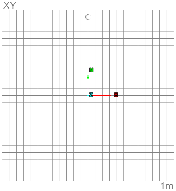
XY, YZ and ZX refer to view window standard axes.
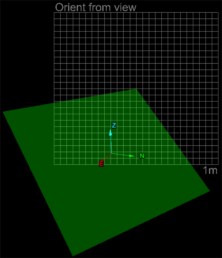
Orient from view places action plane perpendicular to camera view direction (i.e. the user's viewpoint).
Toggle hide or display action plane
On the
View ribbon tab, go to the Action Plane group. Toggle ![]() Visibility to hide
or display the action plane.
Visibility to hide
or display the action plane.
Toggle hide or display action plane manipulator
The action plane manipulator is a widget that can be used to move and rotate the action plane manually.
On the
View ribbon tab, go to the Action Plane group. Click on ![]() Manipulator.
Manipulator.
Initially a white sphere appears, which follows the mouse around on the action plane. Click on the desired location to activate. The translate and rotate widget will appear, allowing adjustments. Drag the manipulator's rings and axis to reposition and re-orient the action plane.
Note: The action plane can only be translated along its normal (i.e. in the direction of the manipulator's axis).

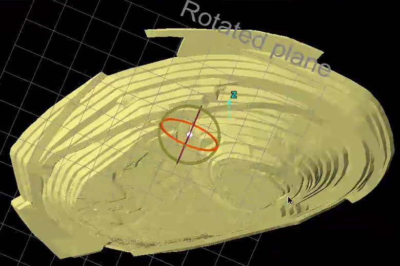
Use manipulator to move and rotate action plane manually.
Click on the white sphere or click on the button again to close the manipulator.
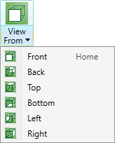
Predefined views
Predefined views allow you to view standard orientations with respect to the current placement of the action plane.
On the view window toolbar or the View ribbon tab, go to the Action Plane group. From the ![]() View From drop-down list select one of the available views.
View From drop-down list select one of the available views.
Save manage and restore action plane
Save any action plane position with a reference name, then recall it later as required.
To quick save an action plane
-
Load the required objects in a view window.
-
On the View ribbon tab, go to the Action Plane group. From the
 Saved Planes drop-down list select Save Action Plane.
Or
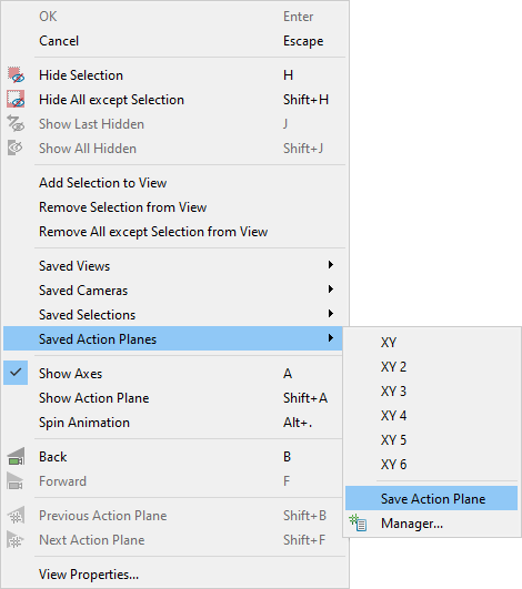
Right-click in the view window hover over Saved Action Planes then click Save Action Plane.
-
Saved planes are listed under the Saved planes menu. Planes saved in this manner are named
XY,XY 2,XY 3etc.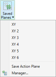
Loading a saved action plane
-
On the View ribbon tab, go to the Action Plane group. From the
Saved Planes drop-down list select an action plane.Or
Right-click in the view window hover over Saved Action Planes then select an action plane.
Or
On the View ribbon tab, go to the Camera group and select
 Previous Action Plane to cycle through views in reverse order or
  Next Action Plane to cycle through views in the forward order.
 -
The current action plane position will be changed to the new action plane position.
To manage saved action planes
-
Load the required objects in a view window.
-
On the View ribbon tab, go to the Action Plane group. From the
Saved Planes drop-down list select  Manager....
Or
Right-click in the view window hover over Saved Action Planes then select
Manager.... -
Enter a name for the saved action plane in the Name field.
-
Click the
 button to save the Plane. The new
action plane object will be added to the Saved
Action Planes name list.
button to save the Plane. The new
action plane object will be added to the Saved
Action Planes name list. -
Click the
 button to remove the selected saved plane from the list.
 -
Planes can be imported or exported using the

 buttons. Clicking
the buttons brings up a browser window where the required location can
be determined.
buttons. Clicking
the buttons brings up a browser window where the required location can
be determined. Planes are saved with the extension
*.pln.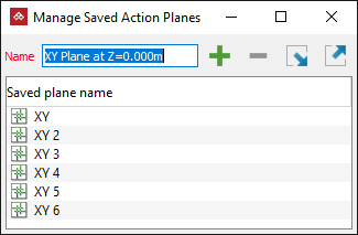
Quick Section
Use this tool to quickly create action planes then create a section.
On the
View ribbon tab, go to the Action Plane group. From the ![]() Quick Section drop-down list select one of the following options.
Quick Section drop-down list select one of the following options.
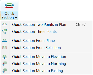
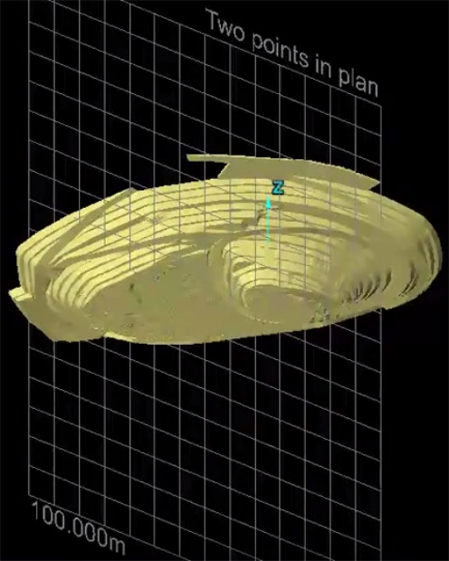
Quick Section Two Points in Plan is also available from the
Position and Filter ribbon tab and navigating to the View group and selecting ![]() Quick Section.
Quick Section.
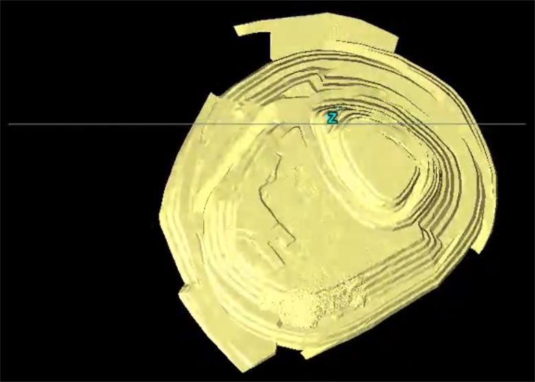
XY Slice
Use this tool to quickly slice objects in a horizontal plane. The elevation is from the middle of the view's extent and the default slice thickness is 10 cm or 0.328 ft.
You will find XY Slice in the
Position and Filter ribbon tab and navigating to the View group then selecting ![]() XY Slice.
XY Slice.
Section view mode
Section viewing mode can be used to check registration errors and to compare objects (for example, compare as-built surface against design).
Section view mode provides the ability to view only a section or strip within the view window with respect to the action plane. Options allow designating reference cuts based on the front, back and centre (strip) of the action plane. Advanced options provide more control on the strip sizing and increments.
-
Select the object.
-
The Section Mode is available from the Position and Filter ribbon tab and navigating to the View group. From the
 Section Mode drop-down list and select a section view.
Alternatively
The Section Mode is also available from the View ribbon tab and navigating to the Action Plane group. From the
Section Mode drop-down list and select a section view.
.png)
- Back Side—to view a section set out in the Section Manager to represent the back side.
- Front Side—to view a section set out in the Section Manager to represent the front side.
- Strip—to view a section set out in the Section Manager that represents a strip between front and the back side.
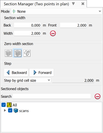
Section Manager
The ![]() Section Manager... provides more precise adjustment of settings for each of the section modes.
Section Manager... provides more precise adjustment of settings for each of the section modes.
|
|
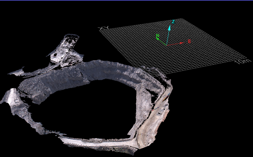
Viewing a horizontal section through a pit using the XY positioned action plane.
