Discontinuity Spacing
The Discontinuity spacing tool helps to build a simple map of spacings between discontinuities. The tool allows you to specify the size to use for comparing overlaps of discontinuities, then examine the spacings between discontinuities with reference to an average orientation or a specific orientation of interest. The graphical results are stored in the geotechnical container. A summary is also displayed in the report window of statistics for individual discontinuity sets as well as a final grouping of all discontinuities. A list of the spacing can be saved to a text file.
-
Start with discontinuities that you've investigated using Extract discontinuities, Query dip and strike, or saved previously.
Multiple sets of discontinuities can be assessed at once. Results will be given for each set as well as for all discontinuities combined.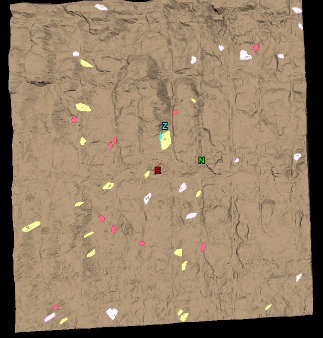
-
On the Geotechnical ribbon tab navigate to the Analyse group and select
 Spacing.
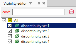
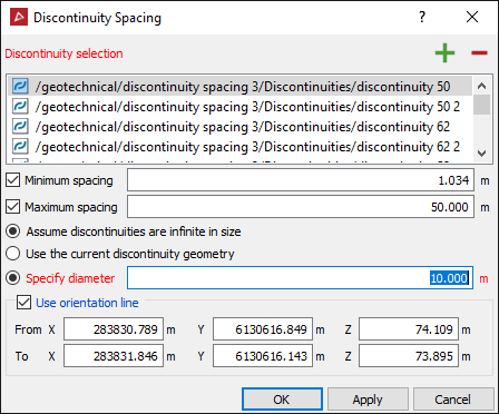
Add existing discontinuity sets or individual discontinuities to the Discontinuity selection list by selecting the discontinuities and clicking the add button or drag and drop the discontinuities into the field. Removing an entry by selecting the discontinuity and click the
  remove button.
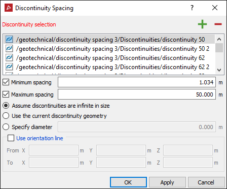
- Adjust settings to refine your analysis. The following are available for helping define the theoretical size of discontinuities or excluding certain spacings.
The following settings are optional:
- Minimum spacing - Spacing less than this will be ignored.
- Maximum
spacing - Spacing greater than this will be ignored.
Choose one of the following methods to define the size of the discontinuities for the purpose of the analysis:
- Assume discontinuities are infinite in size - If this is selected then discontinuities will be treated as infinite planes.
- Use the current discontinuity geometry - If this is selected, then only discontinuities which exactly intersect the orientation line will be counted.
- Specify
diameter - If this is selected, then discontinuities will be
treated as circular discs of the specified diameter located at their
current centroids.
Chose whether to use an orientation line and specify its location:
- Use orientation line - If an orientation line is specified then spacing will be calculated as the distance between discontinuities at the location they intersect the orientation line. Without an orientation line, spacing will be calculated based on the mean discontinuity orientation. Enter coordinates directly into the fields on the panel or select the field(s) and click in the view window where you want to define the orientation line.
-
Click OK or Apply.
New sets of discontinuities will be created
at the location of the input discontinuities, but oriented at the mean
direction for the discontinuity set. Lines are created that represent
the spacings between the nearest discontinuities according to the criteria
entered. Right-click on a discontinuity and chose View
front on or View side on
to see these angles accurately (ensure you are in orthographic
projection mode ![]() , not
perspective).
, not
perspective).
Spacings (represented by lines) can be deleted by manually selecting and removing them in the view window.
Pressing Ctrl + I will cause the properties to be re-calculated and updated, without the need of running the
![]() Discontinuity Spacing tool
again. This can be useful after cleaning up data and deleting incorrect
lines. Delete all incorrect lines, select the remaining lines.
Discontinuity Spacing tool
again. This can be useful after cleaning up data and deleting incorrect
lines. Delete all incorrect lines, select the remaining lines.
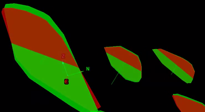
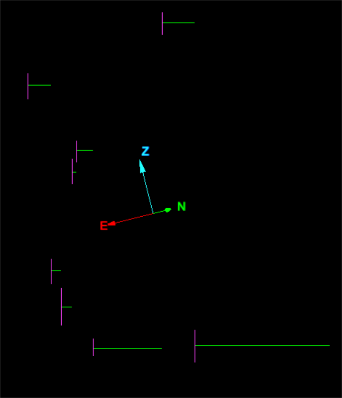
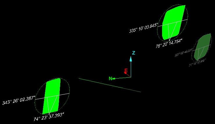
Original discontinuities (green) displayed overlapping their mean-orientation equivalents (red). The green (perpendicular) lines represent the spacings between discontinuities.
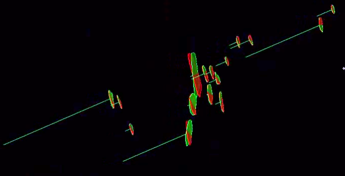
View side on of the mean-orientation equivalents of the discontinuities.
View front on of the average-orientation equivalents of the discontinuities.
The summary of statistics for individual discontinuity sets (if present) as well as a final grouping of all discontinuities will be populated in the report window.
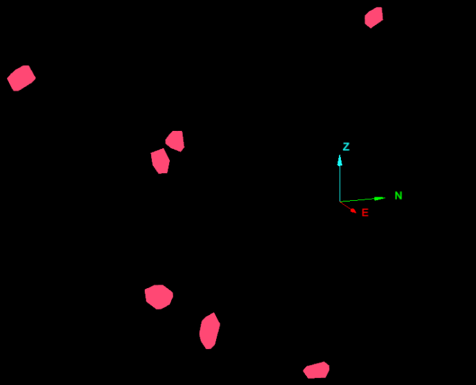
An example analysis using an orientation line and specifying a diameter for the discontinuities. This resulted in only three of the total discontinuities overlapping along the orientation line and two spacings between them.
-
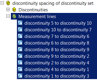
Select the Measurement lines of the discontinuity spacing output files in the geotechnical container.
-
From the Home ribbon tab navigate to the Data group and select
 Export.
 -
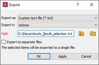
Set Export as as custom text file and the unit to export in.
-
Click OK or Apply.
-
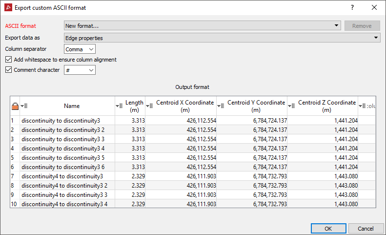
In the Export custom ASCII format panel set the ASCII format type to new format from the drop-down list.
-
Set Export data to Edge properties.
-
Click OK. The discontinuity spacings are exported as a text file.
To save the spacings to a text file do the following: