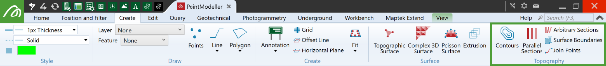
Topography
Source file: topography-group.htm
The Topography group tools enable you to draw lines that identify and highlight topographic detail on scans and surfaces.
|
|
Contours (Alt+K) Create elevation contour lines on surfaces. |
|
|
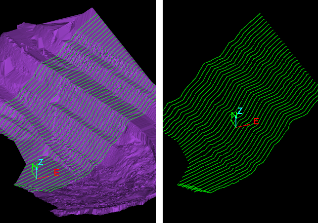
Parallel Sections (Alt+K) Create non-parallel section lines on surfaces at regular intervals. Suitable for straight tunnels. |
|
|
Arbitrary Sections (Alt+/) Create section lines on surfaces at regular intervals. Suitable for curved or irregular tunnels. |
|
|
Surface Boundaries (Alt+\) Draw boundary edges of surfaces. |
|
|
Join Points Create a line joining points in a selection. |
Contours
The Contours tool (Alt+K) allows you to create contours ![]() on surfaces, which are then saved into
an edge network object.
on surfaces, which are then saved into
an edge network object.
To create contours, do the following:
-
Select at least one surface from which to create contour lines.
-
On the Create tab, in the Topography group, click
 Contours.
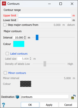
-
Enter the Upper limit and Lower limit for the contour creation, or click on them in the view window.
-
Select the Step major contours from checkbox and enter a datum value to generate contours from a level other than the zero RL. Clear to generate contours from the zero RL.
-
Define the Interval and Colour for the major contours.
-
(Optional) Select the Label contours checkbox and define a Label size and Density of labels (ideally the same size as the interval) to add elevation labels to the major contours.
-
(Optional) Select the Minor contours checkbox to generate minor contour lines between the major contours. Specify a Minor interval and Colour.
-
Select a container for the created contours object in the Destination field. By default, the contours are saved in the
contours container.
|
|
|
Major and minor contours, with the major contours labelled. |

Sections
The Sections
Parallel sections are always in the same orientation, so are best used in relatively straight sections of tunnel.
Create parallel sections as follows:
-
Select the scans to be sectioned.
-
On the Create tab, in the Topography group, click
 Parallel Sections (Alt+/).
 -
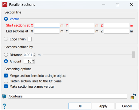
In the Section line area, select one of the options for defining the section line, then enter details according to the following:
-
Vector: Enter the Start sections at and End sections at coordinates, or pick the start and end points in the view window.
-
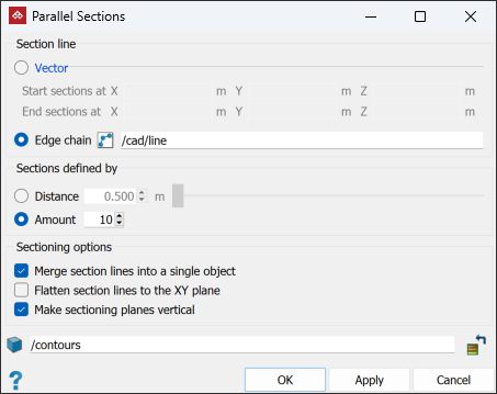
Edge chain: Select an edge chain in the project explorer or view window.
-
-
In the Sections defined by area, select either Distance or Amount, then enter the required distance between sections or the number of sections to be created.
-
(Optional) Choose from the following Sectioning options:
- Select Merge section lines into a single object to create a single edge network representing the parallel section of the object.
- Select Flatten section lines to the XY plane to create edge networks restricted to the XY plane, without any elevation.
- Select Make sectioning planes vertical to create edge networks in planes parallel with the Z axis.
-
Enter the required Destination container or leave it as default.
-
Click OK or Apply. The parallel sections are saved as lines
 in the container specified at step 6.
|
|
|
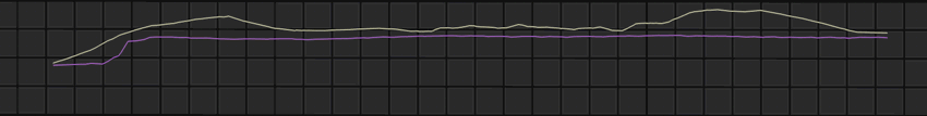
The above example compares two sections from the same surface overlaid to show changes in the surface. |
See also Arbitrary Sections, below.
Create arbitrary sections as follows:
-
Select the scans to be sectioned.
-
On the Create tab, in the Topography group, click
 Arbitrary Sections (Alt+\).
-
On the status bar, enter the start point coordinates, or pick it in the view window.

-
On the status bar, enter the end point coordinates, or pick it in the view window.

-
Create more sections as required and click
 or press Enter to finish. The sections are created as edge networks
  and saved in the contours container.
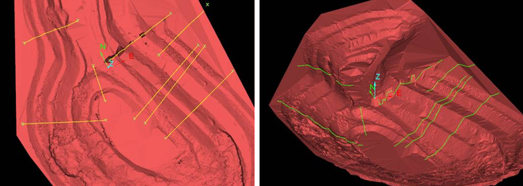
Surface Boundaries
The Surface Boundaries
tool creates edge networks ![]() that define the boundaries of a surface.
that define the boundaries of a surface.
To create a surface boundary:
-
On the Create tab, in the Topography group, click
 Surface Boundaries. Alternatively, on the Query tab, in the Boundary group, click Surface Boundaries.
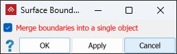
- With
Merge boundaries into a single object
either:
- Select to include all loops in a single edge network.
- Clear to create the edge loops as separate objects.
Or
-
Click OK or Apply to finish.
|
|
|
|
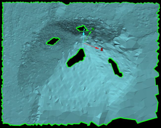
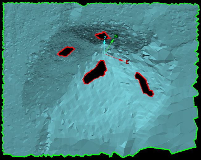
Surface boundaries have been created as a single edge network (left) and as edge loops (right). Edges are represented in green and holes in the surface are represented in red. |
|
Join Points
The Join Points tool joins a selection of points to create a line ![]() following user-defined indexing.
following user-defined indexing.
This enables you to quickly and automatically create an edge chain based on existing data, instead of creating an edge chain manually.
Data used can consist of either single-point or multi-point objects. Expand below for details on each.
Single-point objects can be any of the following:
- Annotations
- Survey points
- Point sets containing only one point
- Scans with only a single point
The tool will create a single edge chain across all selected objects.
The following indexing options are available for single point objects:
-
Position in data explorer. The line will be drawn through points in their order of appearance in the project explorer.
In the example below, the line will be drawn as follows:
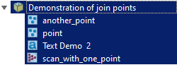
First point in the line will be the point from another_pointNext point in the line will be at pointNext point in the line will be at Text Demo 2The final point in the line will be at scan_with_one_point -
Object tag. The edge chain is created through points ordered by the value of a specified object tag. Objects in the selection without the specified tag are ignored.
This method is useful with multiple scans that cover an area. Tag values can be applied to points in different scans to put them in order before using the Join Points tool. .
-
Point tag. This works similarly to the Object tags method, but uses the value of the point tag of individual points from the object, rather than from the object as a whole. Objects in the selection without the specified tag are ignored.
For instructions on creating tags, see Attributes > Create Attributes.
This is useful if you sequentially named a set of survey points, and sorted them accordingly. You can then easily create an edge chain from the survey points.
Multi-point objects can be:
- Point sets
- Scans with multiple points
- Edge objects
- Facet networks
- Surfaces
The tool will create an edge object for each multi-point object in the selection according to the selected indexing option.
The following indexing options are available for multiple point objects:
-
Point tag. The points of the multi-point object are sorted by the value of the specified point tag, and an edge chain is then created from the position of those points in that order. Objects in the selection without the specified tag are ignored.
-
Point property. Points of the multi-point object are sorted by the value of the specified point property, and an edge chain is then created from the position of those points in that order. Every point in the object must have a value specified, so no points are ignored with this method.
For instructions on creating tags, see Attributes > Create Attributes.
To join points using attributes:
-
Select the objects with points to be joined in the project explorer.
-
On the Create tab, in the Topography group, click
 Join Points.
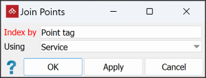
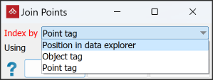
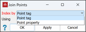
-
From the Index by drop-down, select the option that was used to create the attribute.
-
Select the tag denoting points to be joined from the Using drop-down.
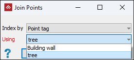
-
Click OK or Apply.
All points in the selected object, with the chosen tag will be joined.
