Create Solid
Source file: discontinuity-solid.htm
The Create Solid tool allows you to construct a solid using discontinuity planes and any other planes you define. This allows you to construct a solid representing a broken wedge of rock or similar, that may fall away from a rock wall.
To create a discontinuity solid, proceed as follows:
-
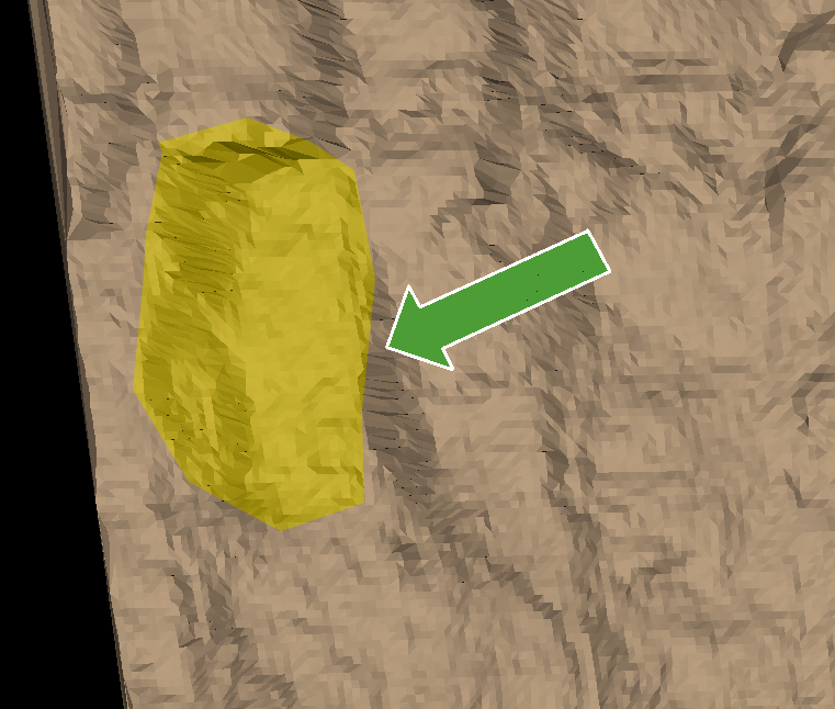
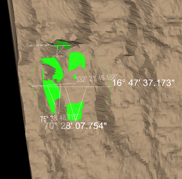
Select the area where you wish to build the discontinuity solid.
-
Use existing discontinuities or create new discontinuities that represent the sides of the solid in contact with the rock wall surface.
Tip: Use Query dip and strike or Extract discontinuities to create new discontinuities. See Dip and Strike > Query and Extract.
- On the Geotechnical tab, in the Analyse group, click
 Create Solid.
 -
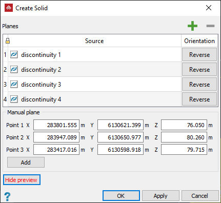
Add the discontinuities representing the sides of the solid to the Planes list by selecting them and clicking the
 button, or by dragging the discontinuities into the field. Remove an entry by selecting the discontinuity and clicking the
  button.
Click Reverse for any discontinuity plane whose opposite side is needed as a reference in creating the discontinuity solid.
button.
Click Reverse for any discontinuity plane whose opposite side is needed as a reference in creating the discontinuity solid. - Define Manual planes by clicking in any coordinate field for a point, then selecting points around the rock wall where external planes of the solid intersect. You can also manually input numerical values for the coordinates of the points. Click Add to add the plane to the Planes list for the solid. A preview visualisation of the solid will be updated.
-
Click Hide preview or Show preview to toggle a visualisation of the solid.
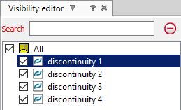
Tip: Use the visibility editor to hide and show other elements around the solid.
-
Click OK or Apply to save the solid. The result is a solid object saved in the
surfacescontainer.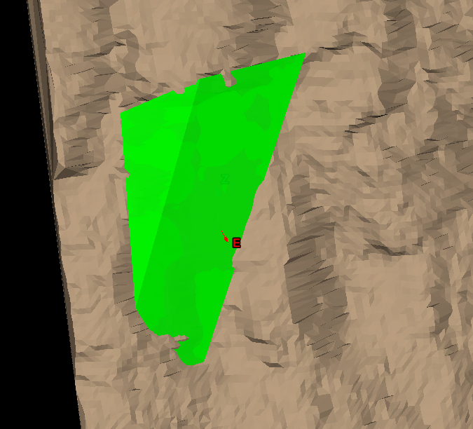
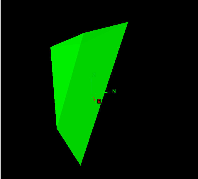
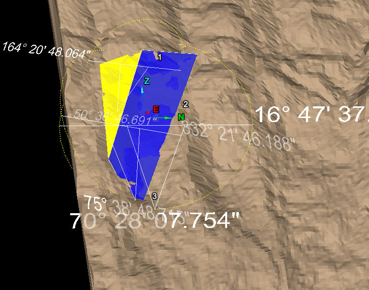
As you add planes, a preview visualisation of the solid will appear in the view window.
Repeat to add more planes, as required to continue refining the shape. The tool will automatically extend and trim the planes, where appropriate.