Edit
Source file: edit-discontinuities.htm
The Edit group tools that enable you to edit discontinuity objects and annotations.

|
|
Edit Annotations Edit a discontinuity annotation. |
|
|
Merge Merge similar discontinuities. |
|
|
Set Length Specify the length of a discontinuity from two points. |
|
|
Convert Discontinuity Convert a discontinuity to a surface, polygon to strike line. |
|
|
Add Points Extend a tangent plane by adding points. |
|
|
Extend to Intersection Extend two or three discontinuities until they intersect. |
|
|
Extend to Surface Extend selected discontinuities until they intersect a surface. |
Edit Annotations
The Edit Annotations tool
allows you to choose the colour of discontinuity text annotations.
-
In the Geotechnical tab, in the Edit group, click
 Edit Annotation.
 -
Select the discontinuities
 to be edited.
 -
Choose colour by clicking on the colour box to open the colour swatch. Select a colour from the available options.

-
The colour is instantly applied.
|
|
|
Selected colour (red) applied to discontinuity annotations (text). |
Merge
The Merge tool
enables you to blend overlapping discontinuities that are close
enough to meet the parameters specified in the input fields. The discontinuities
can be the result of the  Extract
discontinuities tool, or gathered from other analyses and observations.
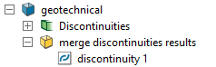
A new container is created which stores the merged discontinuities.
Extract
discontinuities tool, or gathered from other analyses and observations.
A new container is created which stores the merged discontinuities.
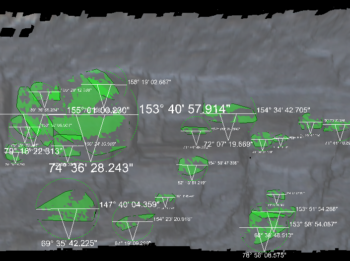
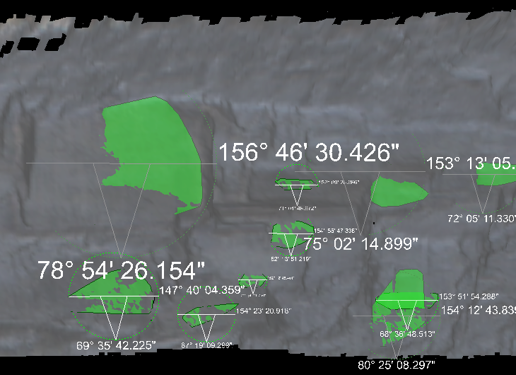
This tool aims to avoid data duplication where discontinuities are so similar that they almost coincide and would be better represented as a single discontinuity. The result is a new single discontinuity that encapsulates the total area of the original overlapping discontinuities. Merging discontinuities avoids incorrect bias in objects such as stereonets, where overlapping, similar discontinuities can incorrectly increase concentration of data points.
To merge discontinuities:
-
On the Geotechnical tab, in the Edit group, click
 Merge.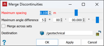
-
Specify the Maximum spacing between the planes of the discontinuities and the Maximum angle difference. Discontinuities closer than the spacing setting and within the angle difference will be merged.
-
(Optional) Select Merge across sets to allow comparisons across different sets of discontinuities.
-
Select appropriate discontinuities
or discontinuity sets  for grouping and click Apply or
OK.
for grouping and click Apply or
OK.
The tool cycles through the selected discontinuities, applying
the criteria to two discontinuities at a time and merging them if
appropriate. The results are placed in the geotechnical
container.
|
|
|
|
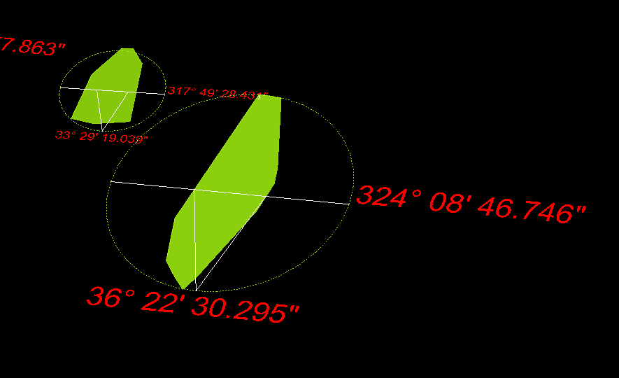
Example of merging discontinuities - before (left) and after (right). |
|
Set Length
The Set Length tool enables you to edit the length of a discontinuity. Proceed as follows:
-
Choose a single discontinuity
to alter from the discontinuitiescontainer. -
On the Geotechnical tab, in the Edit group, click
 Set Length.
 -
Pick two points to change the length of the discontinuity.
-
Click
 or
or  or press Enter to complete the process.
-
Clicking cancel
 or Esc will exit the process.
Convert Discontinuity
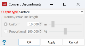
The Convert Discontinuity tool enables you to convert discontinuities to a surfaces, bounding polygons, or strike lines or normal lines. Proceed as follows:
-
Select the discontinuities
to be converted. -
On the Geotechnical tab, in the Edit group, click
 Convert Discontinuity.
 -
Choose type of output needed.
-
Click OK or Apply.
Add Points
The Add Points tool enables you to add a new point to a discontinuity.
Note: You can only access this tool from the Geotechnical tab if at least one discontinuity is selected. However, it will only work if only one discontinuity is selected. To add points to another discontinuity, repeat the procedure below.
To add points to a discontinuity:
- Select the subject discontinuity .
-
On the Geotechnical tab, in the Edit group, click
 Add Points.
The status bar will display the Point to add tool.

-
Click at the location of the new point, or enter coordinates in the digitisation request and click
or press Enter.The new point will snap to the discontinuity’s tangent plane.
-
Repeat step 2 to add more points, as required.
-
To complete the tool and retain the new points, right-click anywhere in the view window, or click
in the status bar. -
To exit and discard the new points, press Esc or click
in the status bar.
Extend to Intersection
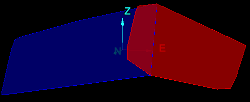
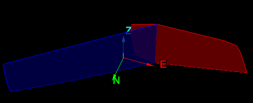
The Extend to Intersection tool enables you to to visualise discontinuities, as though they were spread across an entire pit, showing where they would appear if they were to extend until they intersect each other.
Note: There is no panel to populate.
To extend discontinuities to intersection:
-
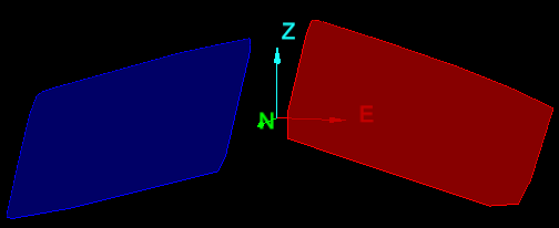
Select discontinuities
in the project explorer.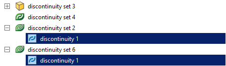
-
On the Geotechnical tab, in the Edit group, click
 Extend to Intersection, or right-click one of the discontinuities and choose Extend to Intersection.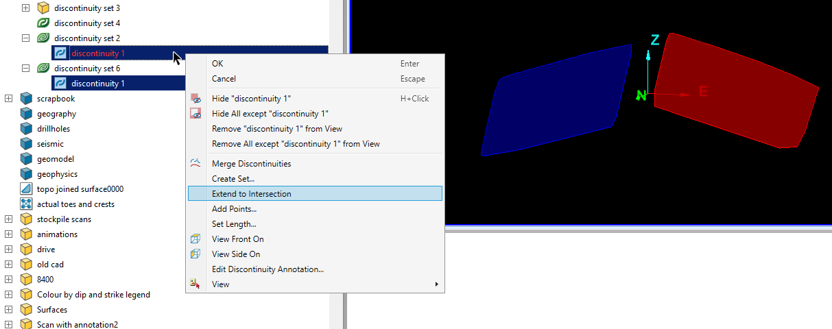
-
PointModeller will extend the selected discontinuities until they intersect each other.
Extend to Surface
The Extend to Surface tool helps to visualise discontinuities, as though they were spread across an entire pit. It shows where they would appear in other areas of the pit, and any effects such as intersections with other discontinuities. It can extend discontinuities across an entire pit, across blast block solids and across pit advancement solids.
To extend discontinuities to a surface:
-
Select discontinuities
in the project explorer.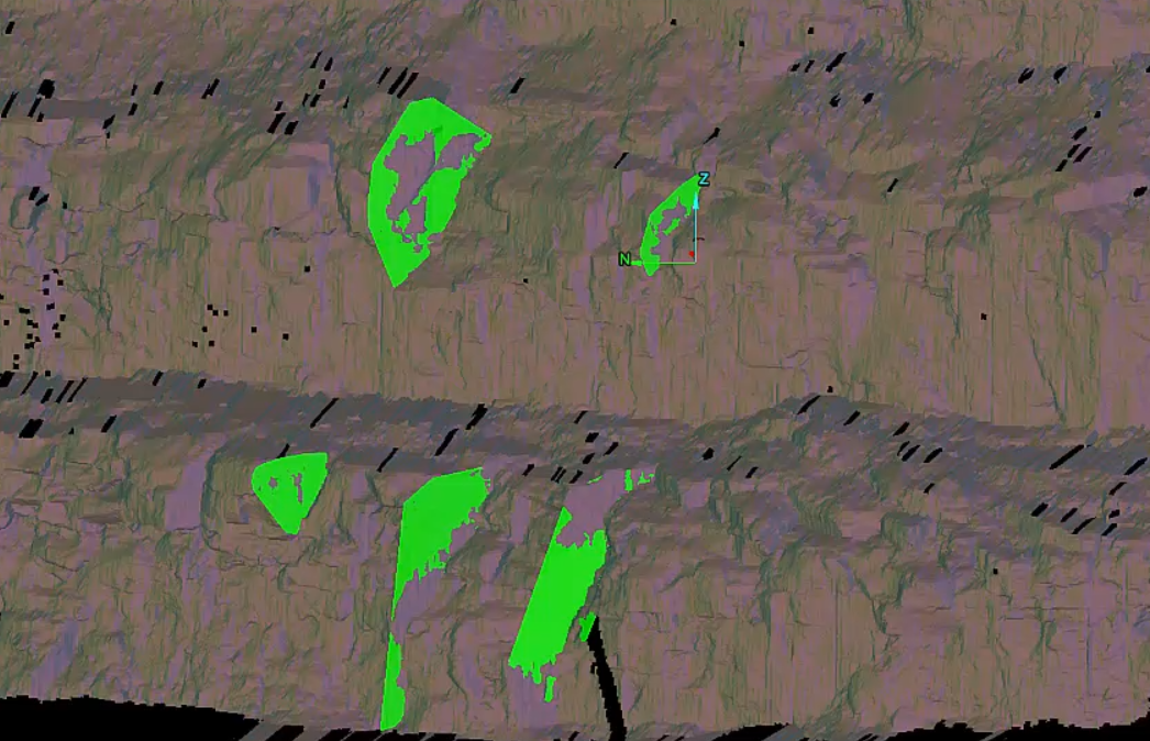
-
Select the surface (pit area) of interest.
-
On the Geotechnical tab, in the Edit group, click
 Extend to Surface.
 -
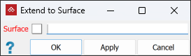
Import the surface into the panel.
-
Click OK or Apply.
A large plane will be drawn through each discontinuity and extended through the volume of the entire selected surface. You can see where they would extend to if they were to continue through the pit. You will also see any discontinuity intersections and where they will occur around the pit.
|
|
|
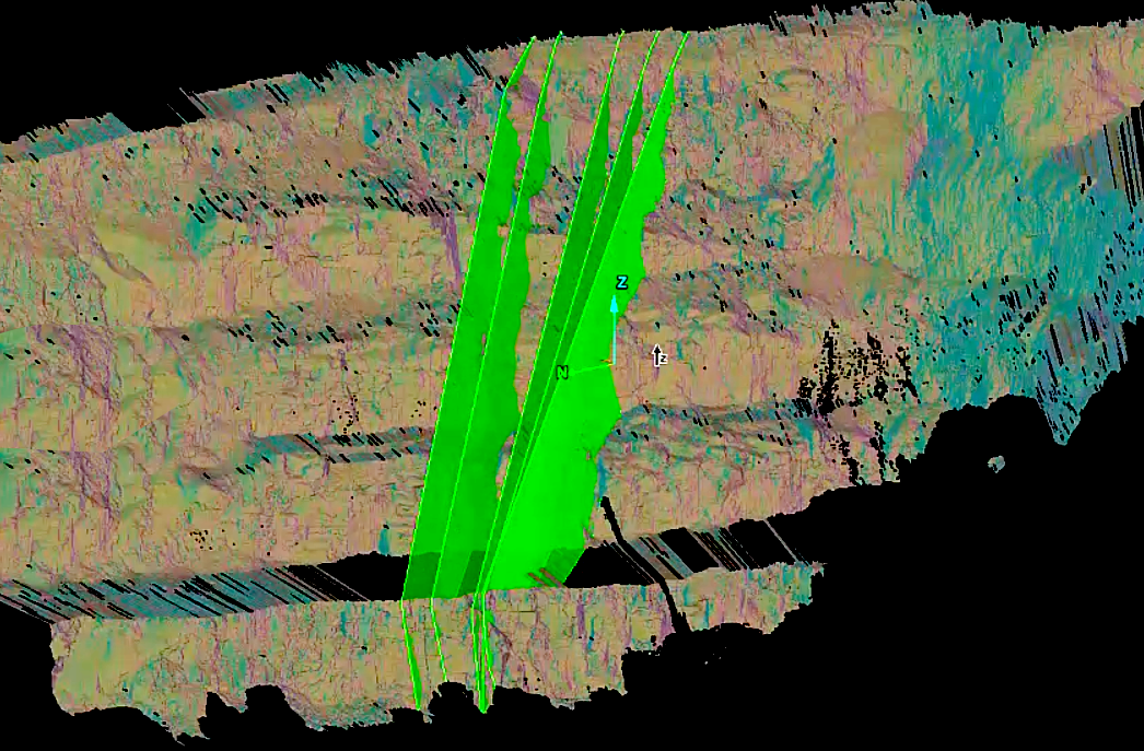
Discontinuities extended through the pit. |