Discontinuities, Dip and Strike
Discontinuities are defects or faults within rock bodies that can destabilise the structure. These can be analysed with the PointModeller Geotechnical tools to identify potential failures.
Discontinuities are not only defined by their physical locations, but also by their dip angles and strike directions as described below.
Dip and strike defined
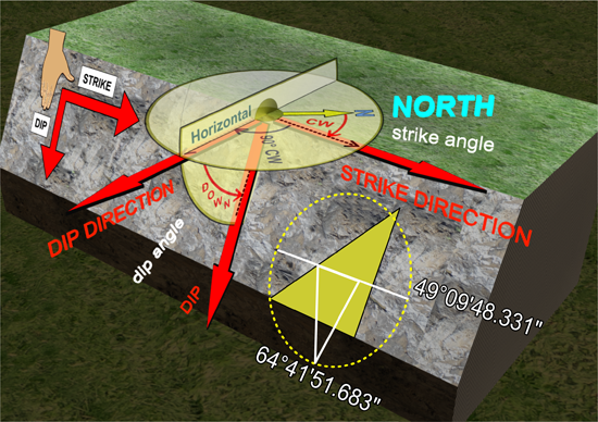
Dip and strike must be defined in order to ensure consistent results. PointModeller uses the 'American right hand rule' method for defining dip and strike.
|
|
|
|
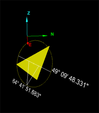
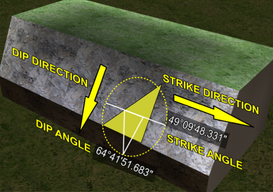
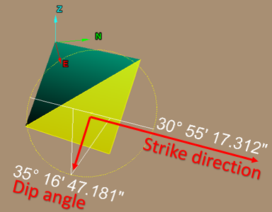
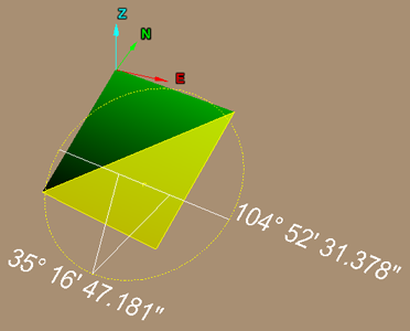
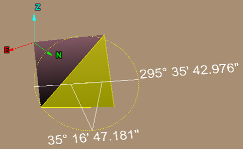
PointModeller identifies dip and strike of sloping faces by highlighting segments and drawing a yellow circle around these. A white horizontal line is also drawn with a 'V' shape pointing down in the direction of the dip. The strike angle (clockwise from north) is identified on the side of the circle in the strike direction. The dip angle (down from horizontal) is specified at the bottom of the shape. |
|
Determining dip and strike
-
To determine dip and strike manually:
-
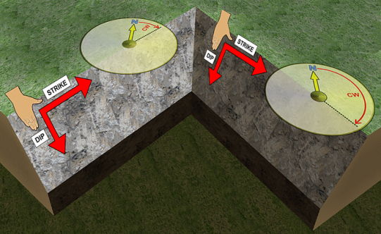
Place right hand palm down.
-
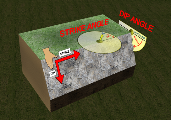
Point the fingers down the slope. This is the dip direction. The dip angle is measured down from the horizontal.
-
The right thumb points in the direction of the strike. The strike angle is measured clockwise from the north direction.
-
|
|
|
A Strike angles for each face determined clockwise from north. |
|
|
|
The Dip angle is the angle measured down from a horizontal line to the slope or dip line. |
|
|
|
Example depicting the Dip and Strike along with elements showing the full derivation. |
|
|
|
|
|
|
Samples showing various orientations of a single plane, with respect to north. The plane has only been turned around the Z axis. Note the number on the right indicating strike angle. The dip angle remains constant. |
|||
