Dip and Strike
Source file: dip-strike-group.htm
The Dip and Strike group tools enable you to identify and analyse discontinuities.

|
|
Smart Query Create a discontinuity from a single click on a surface or point cloud. |
|
|
Query Create a discontinuity from a point selection. |
|
|
Extract Create multiple discontinuity objects of a similar orientation. |
|
|
Create Set Group discontinuities into a set. |
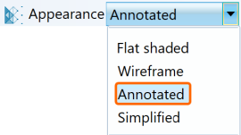
Discontinuity objects can be displayed in
different formats to suit the operator's preferences. Select the discontinuities
in the geotechnical container
and apply a suitable surface appearance from the Home > Colour tool group. Options include
flat shaded surface, wireframe, annotated, and simplified. See Appearance.
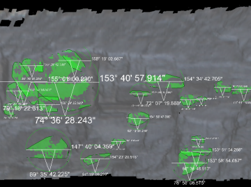
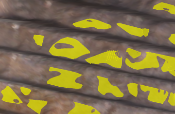
|
|
|
Discontinuities displayed as Annotated (left) and as Flat shaded (right). |
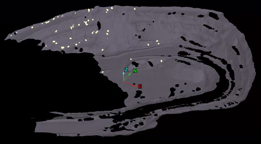
Smart Query
The Smart
Query tool allows you to focus on picking individual
discontinuities. Only one discontinuity at a time can be picked,
but the settings of the tool allow you to adjust the plane fitting tolerance so that the whole discontinuity is identified.
The
individual discontinuity objects that
are created will be saved in the geotechnical
container.
Proceed as follows:
-
Load surfaces

 or point clouds


 of interest into a view window and ensure they are selected in the project explorer.
 -
On the Geotechnical tab, in the Dip and Strike group, click
 Smart Query.
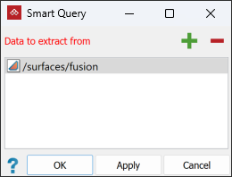
-
Click OK or Apply.
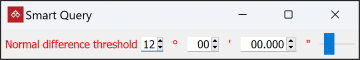
After initialisation, a secondary panel will appear.
-
Select a structure of interest. A discontinuity
 object will be created in the
 geotechnicalcontainer.Note: In selecting a structure of interest, you can either pick a single point, or select a region of points on the structure.
-
Adjust the Normal difference threshold angle in the secondary panel, so that the discontinuity object fully covers the structure. Normal difference threshold defines the allowable variation in angle of the observed discontinuity. Expanding the threshold makes the discontinuity object larger. Reducing the threshold makes the discontinuity object smaller.
Tip: If the discontinuity object does not fully cover the structure, or should cover the same structure across multiple benches, hold down Shift and click where you want to expand it.
-
Repeat steps 4 and 5 to create more discontinuity
objects.
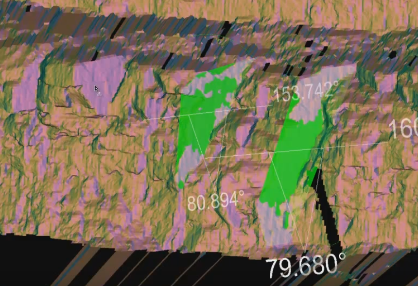
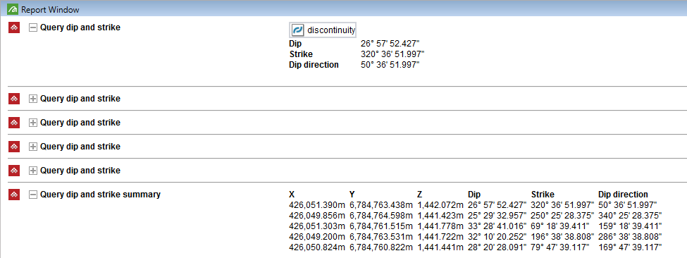
Query
The Query tool displays the dip and strike of a feature, which can be saved as a discontinuity ![]() object.
object.
To query dip and strike, proceed as follows:
Tip: If mapping discontinuities on a scan, display the scan with its points connected and coloured as a photographic surface for optimal viewing.
-
Load the data in a view window and ensure it is selected in the project explorer.
-
From the Geotechnical tab, in the Dip and Strike group, click
 Query.
The query tool appears in the status bar.

-
With the
 (Select points) type, select the structure to be queried in the view window.
The dip and strike are calculated for the selections and displayed with transient geometry in the view window.
Tip:
 Freehand Selection Mode is most suitable when mapping structures.
 -
Click the
 or press Enter or Space to save the discontinuity object.
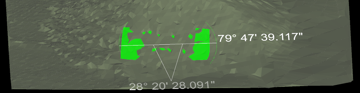
The discontinuity object is saved in the
geotechnicalcontainer and displayed in the report window. -
Repeat for remaining discontinuities to be mapped.
-
Click
 or press Esc when finished to complete the operation, a
summary list of all queries is displayed in the report
window.
or press Esc when finished to complete the operation, a
summary list of all queries is displayed in the report
window.
Extract
The Extract tool
automatically creates discontinuity ![]() objects of similar orientations from an initial selection of points. This its helpful, for example, in
identifying similar fault planes.
objects of similar orientations from an initial selection of points. This its helpful, for example, in
identifying similar fault planes.
-
Select the data to be analysed in the project explorer.
-
On the Geotechnical tab, in the Dip and Strike group, click
 Extract.
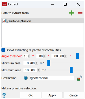
-
With the
(Select points) type, select the structure to be queried in the view window. This structure and others of a similar orientation will be indicated in the view window as transient geometry. -
Select Avoid extracting duplicate discontinuities to avoid redundant results.
-
Adjust the following extraction parameters:
-
Angle threshold defines the angles between which other planes will be considered similar to the original plane of selection.
-
Minimum area defines the minimum surface area in which to fit a discontinuity object.
-
Maximum area defines the maximum surface area in which to fit a discontinuity object.
-
-
Click Apply or OK to save the discontinuity objects.
The discontinuity objects identified will be saved in a discontinuity set container and displayed in the view window.
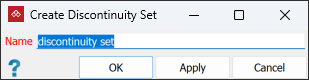
Create Set
The Create Set tool enables you to group and organise multiple objects into sets. Discontinuity objects can be grouped into logical sets to be passed to other tools more conveniently.
-
To create a discontinuity set
 , proceed as follows:
-
On the Geotechnical tab, in the Dip and Strike group, click
 Create Set.
 -
Select the discontinuity
objects in the project explorer to be
included in the set. -
Enter a suitable name for the new discontinuity set in the Name field.
-
Click OK or Apply to complete.
-
Alternatively:
-
Select the discontinuity
objects in the view window. -
Right-click on one of the discontinuity objects in view for the context menu and select Create set....
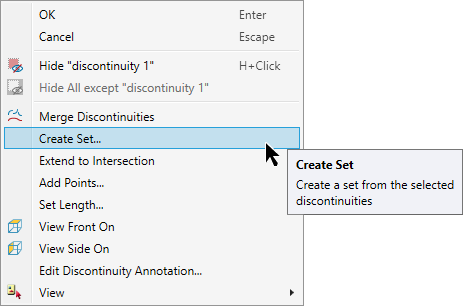
A new discontinuity set will be created
in the geotechnical container
with the selected discontinuity objects.
Tip: You can add more discontinuity objects to a set by dragging them into the set container.
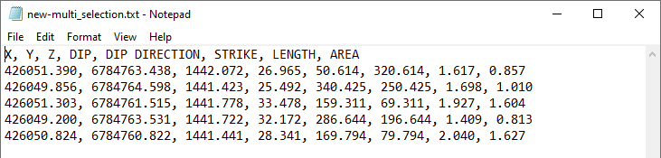
Exporting discontinuity objects
-
To export discontinuity objects as CSV text files:
-
Select the discontinuities
to export. -
From the Home tab, in the Data group, click
 Export.
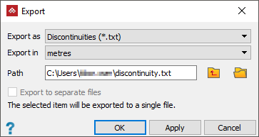
-
The discontinuities can be grouped into one file, or exported to separate files.
-
|
|
|
Resulting text file of group export. |