Export
Source file: export-data.htm
The Export tool (Alt+F3) enables you to export data and objects in different formats to share and open in different applications. The file format options available depend on the types of data selected. Expand below to learn about each option.
Descriptions of data types
|
.maptekobj |
The Maptek object file format allows the user to transfer objects, or any arbitrary groups of objects (excluding referenced external files), between projects. All data can be stored in one file (for ease of sharing) or individually in separate files. |
|
.00t |
Maptek Vulcan software design data format: facet data only. Compatible with non-compressed format used before Vulcan version 8.0, and compressed format used in Vulcan version 8.0 and later. |
|
.arch_d |
Maptek Vulcan software archive format: points and edges |
| .bmf | Vulcan block model |
|
.csv |
Comma delimited ASCII file:
|
| .dgd.isis | Vulcan design data file |
|
.dwg |
AutoCAD binary file format |
|
.dxb |
Binary of the .dxf format |
|
.dxf |
AutoCAD file format: point, edge and facet data |
|
.e57 |
The E57 file format is an extensible industry standard for '3D Imaging Data' developed by ASTM International and specified in the 'ASTM E2807 - 11 Standard Specification for 3D Imaging Data Exchange' standard. |
|
.ireg |
Maptek Vulcan software image registration file |
|
.jpg |
JPEG image file |
|
.las |
The LAS file format is a public file format for the interchange of LIDAR data between vendors and customers. |
| .laz |
LASzip scan file |
|
.ma |
Maya ASCII file |
|
.obj |
Wavefront object modelling format: point, edge and facet data |
|
.txt |
Comma or space delimited ASCII files.
|
| .wrl |
VRML 97 file. Point, edge, facet data can be viewed in web browsers, using plug-ins such as the Cortona VRML client. |
Exporting standard supported data
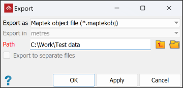
Export standard data as follows:
-
On the Home tab, in the Data group, click
 Export.
The export tool panel will open.
-
Select the data to be exported in the project explorer.
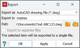
The Export as drop-down list in the tool panel will update according to the type of data selected.
-
Select the required output format from the Export as drop-down list.
-
Where available, select the distance units from the Export in drop-down list.
-
Enter Path to the output location, or browse to it using the
 and
and  buttons.
 -
Some selections will permit you to choose whether to save data as separate or single files. Select or clear the Export to separate files box as required.
-
Click OK or Apply.
Some output formats will require additional criteria to complete the export. Expand the relevant sections below for further detail.
The following constraints apply to exported data:
-
Any data manipulation that has occurred, for example filtering or colouring, will be saved to the file.
-
Newly acquired scans will be exported in their entirety. Data reduction (to reduce file storage requirements) will be performed on scans whose visibility has been manipulated. This process will crop invisible or invalid points from the edges of the scan.
-
AutoCAD files are in the 2018 format specification.
Exporting custom text and CSV file formats
To export a text or CSV file (ASCII file) that is not in one of the predefined PointModeller formats in the data types list above, use the custom text file export method below:
-
Highlight the object or data to export.
-
On the Home tab, in the Data group, click
Export. -
From the Export as drop-down list select Custom text file (*.txt) or Custom CSV file (*.csv).
-
Select the Path (destination directory).
-
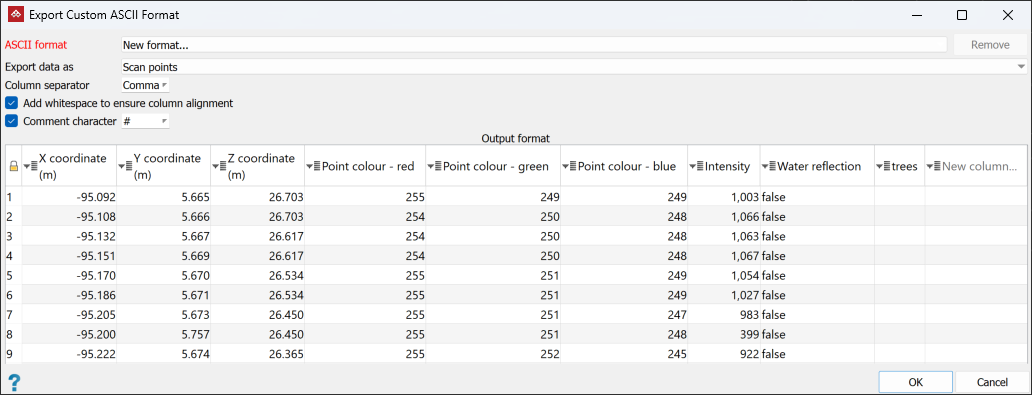
Click OK or Apply. The Export Custom ASCII Format window displays.
-
In the ASCII format field, New format... is selected by default.
Note: You can select any one of a number of pre-defined formats from the drop-down list provided the data to be exported is consistent with the format.
- Select the data type to be exported in Export data as. Different data types can have different attributes:
- Points: Export any details you need and exclude those you don't. Delete and re-order columns as required.
- Scan points: Export any details you need and exclude those you don't. Delete and re-order columns as required.
- Edge properties: Export the midpoint & length of edges.
- Discontinuities: Export discontinuity objects as rows in a CSV file. Each row has the X, Y and Z coordinates of the discontinuity's centroid as well as orientation data (dip and dip direction), and any attributes the object has.
- Ensure the correct Column separator and Comment character options are selected.
-
Ensure the Output format preview columns are arranged correctly. If they are not, change the order by clicking on the column header and choosing the appropriate action from the drop-down list.
-
Click OK.
Exporting images
Image files that are associated with surfaces and scans can be exported, as follows:
Tip: By exporting an image from a scan you can edit it externally,
then re-import it to replace the original image.
-
Select the objects with the associated images to be exported (surface or scan).
-
On the Home tab, in the Data group, click
Export.
You should be able to select the.jpgimage file format for exporting the images. Specify path and or separate file options if appropriate.
Click OK or Apply to continue.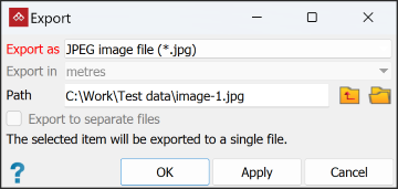
-
If the source images were originally distorted to fit the object, another panel will display providing the option to apply distortion correction. Select or clear as appropriate, then click OK to continue.
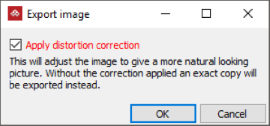
The images will be exported to the specified location.
Exporting 2D text annotations to AutoCAD or VRML
When exporting 2D text annotations ![]() to any of the AutoCAD formats or to VRML, you will be asked to specify units for the text height in the Export panel.
to any of the AutoCAD formats or to VRML, you will be asked to specify units for the text height in the Export panel.
After clicking OK, you will need to enter the required text height.
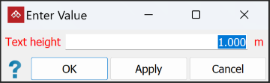
Click OK to complete the export.
