Haul Road Analysis
Source file: haul-road-analysis.htm
Note: Haul Road Analysis is an add-on that requires additional licensing, which may be obtained via your Maptek Account portal. Please see Licensing Applications for details.
Note: Well designed and maintained haul roads are the key to minimising costs and improving productivity. The haul road analysis tool is licensed through Maptek account.
The Haul Road Analysis tool assists in identifying areas of haul roads for possible issues, and allowing changes to the road design to be made.
The haul road analysis tool addresses the following parameters:
- Haul road width
- Haul road grade
- crossfall or camber
- Safety berm or bund height
- Safety berm or bund widths
-
To analyse haul roads, carry out the following steps:
-
Create a 3D CAD surface
 of the mine site.
Note: The input data can be sourced from any type of sensor or package.
-
Import the surface.
-
View the surface in a new view window.
-
Using the
 Line tool create an approximate line along the centre of the road.
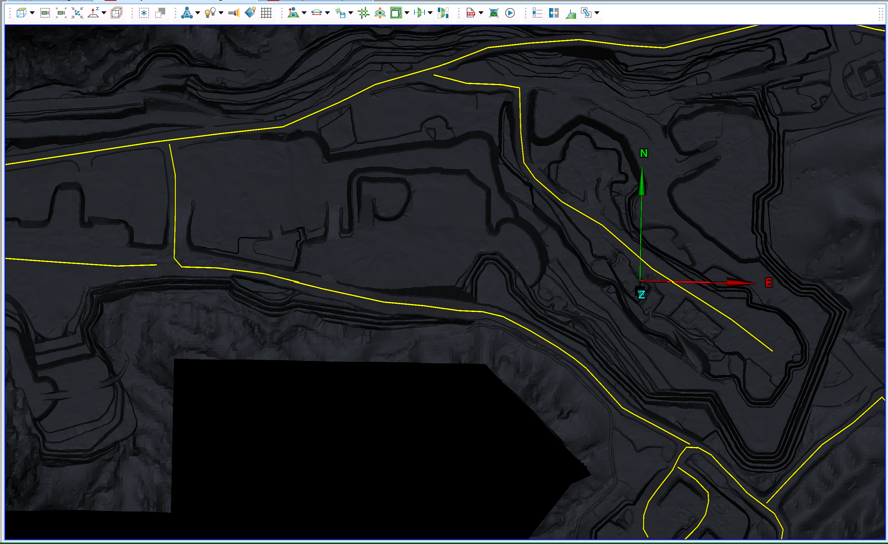
-
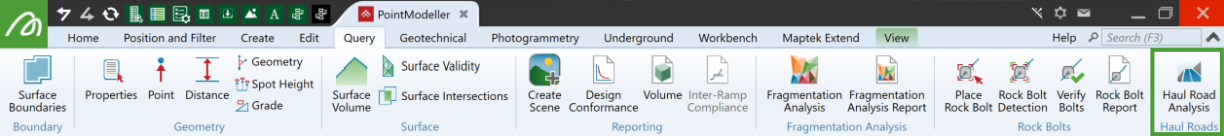
On the Query tab, in the Haul Roads group, click
 Haul Road Analysis.
The Haul Road Analysis panel will open.
-
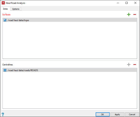
To populate the Data panel, select the surfaces or triangulations of the mine site and the centre lines of the road In the project explorer.
-
Click both the
 buttons to populate the fields with the data. PointModeller will automatically add the objects to the appropriate fields.
 -
Select the Options tab.
-
In the Rules tab you can set Minimum and Maximum values for the following parameters, and define colours to depict the areas of the road that are above, within and below tolerances:
-
Road width
-
Road grade (%)
-
Crossfall grade (%)
Note: If the tool detects an upward grade from the centre line, it too will be flagged as above maximum.
-
Bund height
-
Bund width
-
-
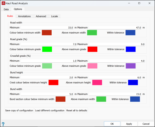
Select the Annotations tab to choose the required annotations. For each measurement, select the required Minimum count for annotation, being the minimum number of contiguous cross-sections meeting the criteria for an annotation to be created.
-
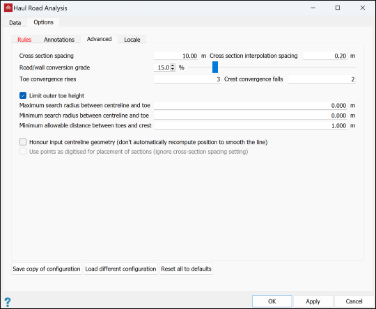
Select the Advanced tab where you can set the parameters below.
-
Cross Section Spacing: Increase or decrease the number of sections by adjusting the cross section spacing.
-
Cross Section interpolation spacing: Intervals at which each section is sampled, looking for grade or change in direction.
-
Road or wall conversion grade: The angle needed in the interpolation spacing to detect a change from haul road to a wall or bund.
-
Toe convergence rises: The number of subsequent upward points needed to create a toe.
-
Crest convergence falls: The number of subsequent downward points needed to create a crest.
-
Limit outer toe height:
-
If selected, the outer toe will be calculated in line with the inner toe height. This is best for pits with spiralling roads.
-
If cleared, all of the outer toe will be drawn to the next closest toe.
-
-
Maximum search radius between centreline and toe: The farthest from the centreline that the tool will search for a toe.
-
Minimum search radius between centreline and toe: The nearest to the centreline that the tool will begin to search for a toe.
-
Minimum allowable distance between toes and crest: The acceptable distance between toes and crest.
-
Honour input centreline geometry:
-
If selected, the tool will use the centreline created by the operator.
-
If cleared, the tool will create a smooth road line by smoothing out any sharp corners in the centreline.
-
-
Use points as digitised for placement of sections:
-
If selected, the tool will create cross sections at the digitised locations.
-
If cleared, the tool will create cross sections equally spaced as specified above.
-
-
-
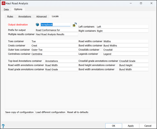
In the Locale tab, select and rename output destination containers as required.
-
Click the buttons at the bottom of the panel per your requirements:
-
Save copy of configuration for later recall for another job.
-
Load different configuration to recall previously saved settings.
-
Reset all to defaults to undo all changes.
-
-
Click OK or Apply.
-
To inspect the results, drag them from the destination containers into a view window.
-
|
|
|
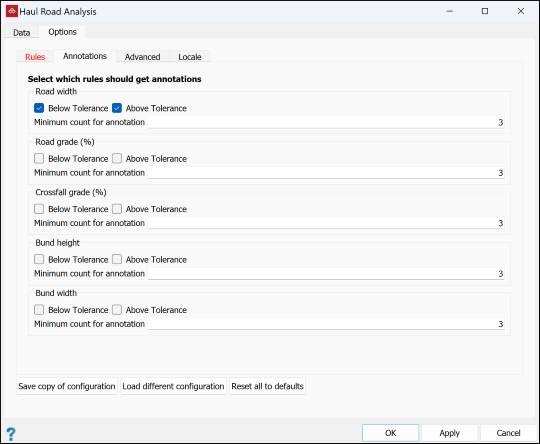
An example of a haul road analysis with all the results grouped and exported into their relevant containers. The legends are compiled from the option rules. Annotations are for road widths only. |
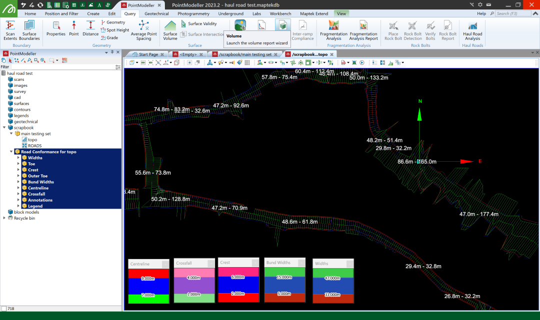
Tip: The Widths lines and the Crossfall lines will overlap each other and the colours will mesh. To visualise each line separately use the visibility editor to hide one and view the other.
