Rock Bolts
Source file: rock-bolts-group.htm
Note: Rock Bolts is an add-on that requires additional licensing, which may be obtained via your Maptek Account portal. Please see Licensing Applications for details.
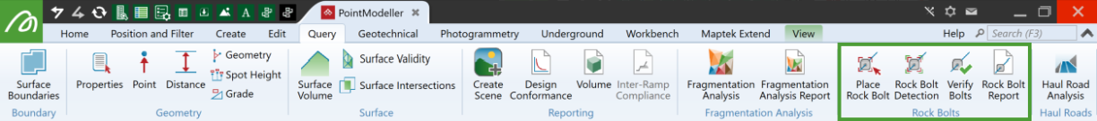
The Rock Bolts group tools enable you to prepare and review rock bolt plans and generate reports.
|
|
Place Rock Bolt Manually place rock bolts. |
|
|
Rock Bolt Detection Automatically detect rock bolts in scans. |
|
|
Verify Bolts Verify detected and created bolts. |
|
|
Rock Bolt Report Generate a rock bolt report. |
Place Rock Bolt
The Place Rock Bolt tool enables you to place individual rock bolts that were missed in the automated process.
A scanner might miss a rock bolt because its line-of-sight is obstructed by other objects, a part of the wall, or protruding rock.
Adding rock bolts
-
To add a rock bolt
 :
:-
On the Query tab, in the Rock Bolts group, click
 Place Rock Bolts.
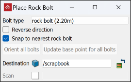
- Name, select, or drag in the Destination container. The default container is
scrapbook. -
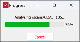
Select the scan where you want to place rock bolts.
PointModeller will automatically analyse the scan for possible bolt locations.
-
Choose a Bolt type to place, or select Manage... from the bottom of the list to create custom rock bolts (see Creating a custom bolt).
Tip: Zoom in to analyse the surface easily.
-
Move the mouse around the scan and locate the missing rock bolts.
- Initially the new rock bolt will be coloured orange and will follow the mouse around the scan.
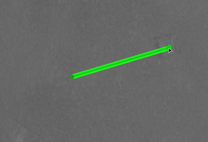
- The new rock bolt will turn yellow when near a possible valid location, and green when snapping to a location.
- If the rock bolt looks like it will be placed in the wrong direction, select Reverse direction. This may result from having multiple scan origins such that the inside of the tunnel cannot be distinguished from the outside of the tunnel.
- Clear Snap to nearest rock bolt if the snapped location (green) is not satisfactory.
- Click to anchor the bolt. Its colour will change according to the Bolt type.
Tip: With Reverse direction selected, you can click on Orient all bolts to reverse the direction of all manually placed bolts.
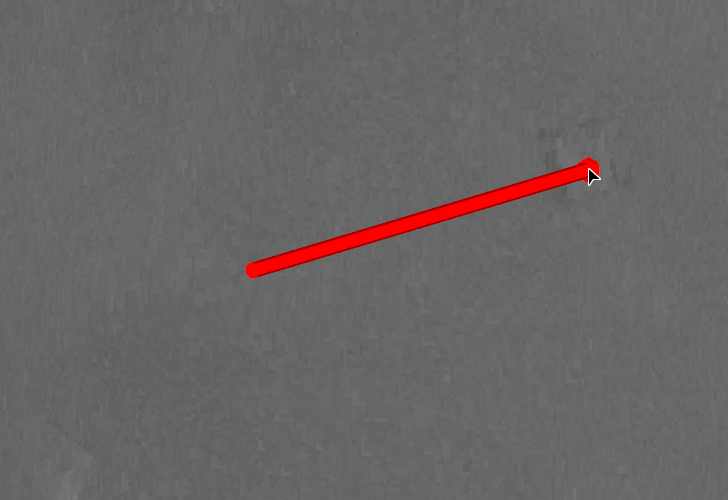
Note: You don't have to wait for the bolt to change colour to place it. If you are confident the bolt is in the right position even when red, click to anchor it.
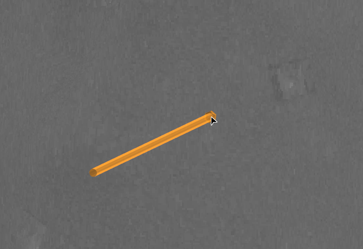
Orange bolt follows the mouse while looking for missed bolts.
Orange bolt snaps to a potential rock bolt location and turns green.
Click to acknowledge the position as a rock bolt; rock bolt turns the specified colour.
- Repeat steps 4 and 5 until all missing bolts have been placed.
- Click Update base point for all bolts to ensure that they are inserted in the tunnel surfaces to the right depths.
Tip: If you move the cursor back over the rock bolt, its colour will change to red. You can then click on it again to remove it.
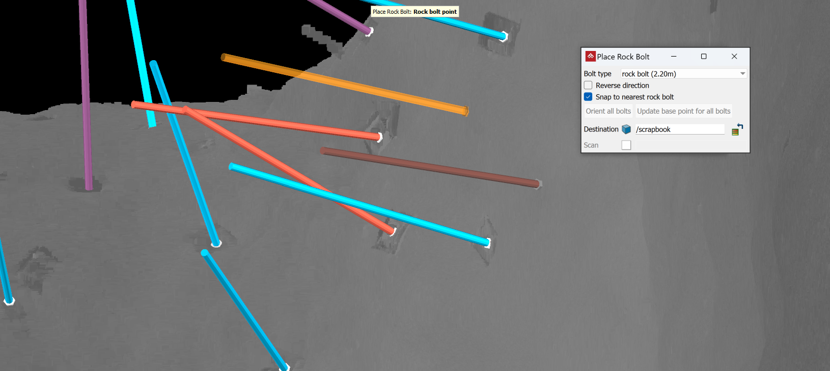
In the above example the different colours represent a rock bolt in place (blue), a split set bolt in place (brown), and a cable bolt in place (purple).
-
Removing incorrectly placed rock bolts
-
To remove an incorrectly placed rock bolt
:-
Move the mouse pointer near the bolt so that the bolt turns red.
-
Click and move the cursor away.
The rock bolt will be removed.
-
Rock Bolt Detection
Source file: rock-bolts-group.htm
The Rock Bolt Detection tool locates rock bolts on scans automatically.
Locating rock bolts automatically with Rock Bolt Detection
-
To locate rock bolts
automatically:-
On the Query tab, in the Rock Bolts group, click
 Rock Bolt Detection.
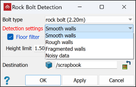
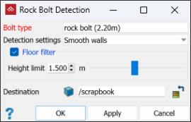
The Rock Bolt Detection panel appears.
-
From the Bolt type drop-down list, select a bolt type to search for, or select Manage... to create a custom bolt (see Creating a custom bolt below).
-
Select Floor Filter and enter a Height limit to set the minimum scanning height (meters). Only points above this limit will be scanned.
-
Name, select, or drag in the Destination container. The default container is
scrapbook. -
Click OK or Apply. The rock bolt detection tool will find all the rock bolts and place them in a sub-container labelled
rock bolts.
-
Creating a custom bolt
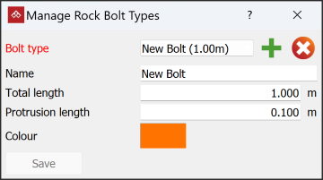
If a bolt type is not available in the drop-down list, you can create it using the rock bolt type manager tool. To create a custom bolt, select Manage... from the Bolt type drop-down list of the rock bolt detection tool.
Enter the new bolt type's details as appropriate and click Save.
|
|
|
In the above example we created a custom bolt type named New Bolt that is 1 m long, with a protrusion of 10 cm, to be coloured orange in the view window. |
Verify Bolts
The Verify Bolts tool allows you to check automated rock bolt detection results and remove any false positives. False positives may result from other objects inside the tunnel that resemble rock bolts.
-
To verify automatically-detected rock bolts
, follow these steps:-
On the Query tab, in the Rock Bolts group, click
 Verify Bolts. The Verify Bolts panel appears.
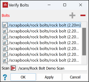
-
Review and flag each rock bolt:
-
In the Bolts list, select the rock bolts you want to analyse.
 Expand for detailed instructions
This field requires a rock bolt selection.
- To add items to the list, select individual rock bolts or containers of rock bolts in the project explorer, and click
 . Alternatively, drag and drop a selection of rock bolts from the project explorer into the list.
 - Click
 to remove items from the list.
- To add items to the list, select individual rock bolts or containers of rock bolts in the project explorer, and click
- In the Scan field, specify the source scan to verify the rock bolts against.
-
Click OK or Apply.
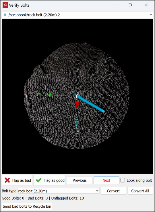
The Verify Bolts window will open and display a small section of the scan surrounding the rock bolt to analyse more closely.
Inspect the bolts one at a time.
Select Look along bolt to align the viewing angle with the bolt's axis. You can still maximise the window to full screen, zoom in or out, and rotate the image to achieve the best viewing angle for your decision.
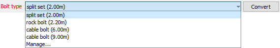
Click Bolt type and select the correct type from the drop-down list. If it is not listed, click Manage... to create a custom bolt (see Creating a custom bolt).
For a positive detection, click
 or for a false positive detection, click
  . The next bolt in the list will then be displayed.
Click Next or press Ctrl+↓ to move to the next bolt, leaving the current one unflagged.
Click Previous or press Ctrl+↑ move to the previous bolt, leaving the current one unflagged.
Press Ctrl+→ to flag the current bolt and move to the next bolt.
Press Ctrl+← to flag the current bolt and move to the previous bolt.
Click Send bad bolts to Recycle Bin to remove the bolts flagged as bad from the list.
 Tip
TipStep through the list, either flagging bolts or leaving them unflagged, as follows:
-
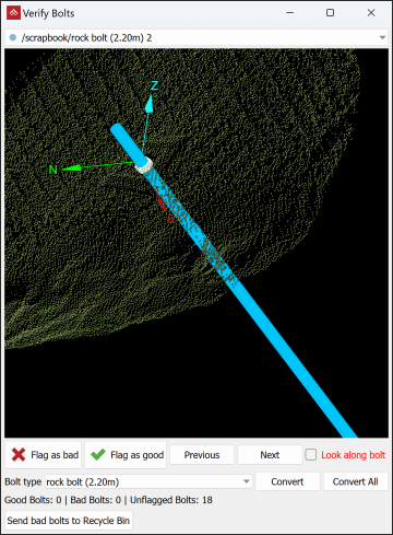
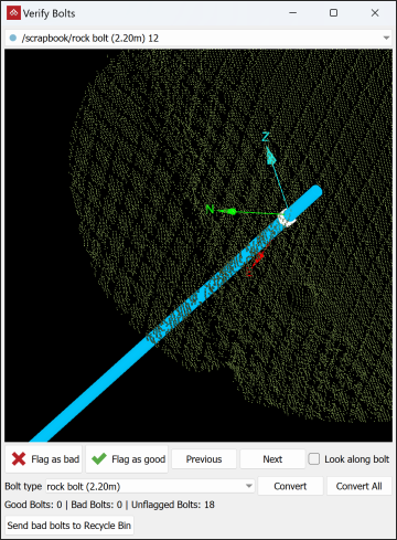
|
|
|
A positively detected rock bolt (left) compared to a false positive detection (right). |
Rock Bolt Report
The Rock Bolt Report tool allows you to generate a PDF report that visually and numerically summarises the distribution of rock bolts.
Preparing the data
-
Follow these steps to prepare the report data:
-
On the Query tab, in the Rock Bolts group, click
 Rock Bolt Report to open the Rock Bolts Report panel.
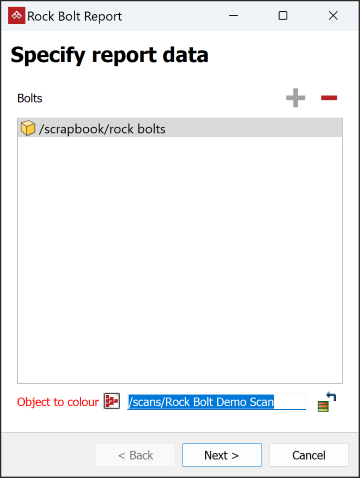
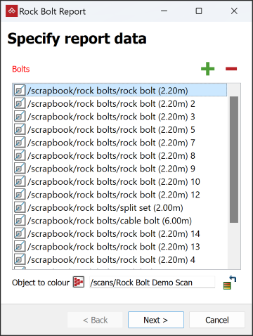
- Select individual rock bolts or select the whole
Rock Boltscontainer and click. - Click in the Object to colour field then select the object to be used to generate screenshots that indicate areas with problematic bolt spacing. This will most likely be a scan the bolts were created from.
- Click Next >.
- Select individual rock bolts
-
Configure report panel will open to adjust the look of the report and the data that will be displayed. Select the required options in the subsections as follows:
-
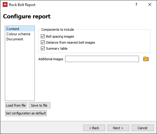
From the Content section, choose components to include.
- Bolt spacing images
- Images of the scan surface coloured by the distance from the nearest bolts
- Summary table
- Any Additional images relevant to the job
-
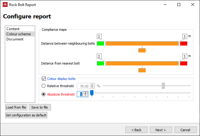
Set the Colour Scheme for the rock bolts and the cut-off distance between them.
-
Adjust the Compliance maps as required. See Modifying a colour scale for detailed instructions.
- Select Colour display bolt to colour the bolt objects as well.
- Select Relative threshold to set the % of neighbouring bolts that fall beyond a colour boundary. Or
- Select Absolute threshold to give an explicit number of bolts instead of a percentage. For example, if a bolt is connected to 4 neighbouring bolts, one 0.5 m away, two 2.5 m away, and one 3.5 m away then, based on the compliance maps above:
- An absolute threshold of 2 or 3 would cause that bolt to be coloured orange, because only one neighbour is ≥ the 3 m cut-off, but 3 of its neighbours are ≥ the 2 m cut-off.
- An absolute threshold of 1 would cause that bolt to be coloured red, because at least one of its neighbours is ≥ the 3 m cut-off.
- An absolute threshold of 4 would cause that bolt to be coloured green, because only 3 of its neighbours are ≥ the 2 m cut-off.
Expand for detailed instructions
-
-
In the Document section, add any required metadata and set a page layout.

-
-
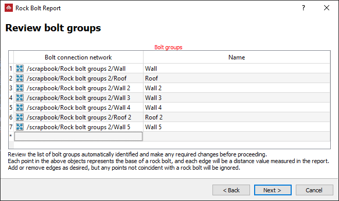
Click Next > to progress to reviewing the bolt groups. The Review bolt groups panel will open displaying the edge networks it has created, grouped by walls and roofs.
Note: Leave the Review bolt groups panel open.
-
Select the
Rock bolt groupscontainer from the project explorer and load it in a new view window to find any inconsistencies. The rock bolt groups are displayed as edge networks. Each group will be coloured differently.
Note: You can save and recall report configurations to save time for future reports. Use the Load from file, Save to file and Set configuration as default buttons as required.
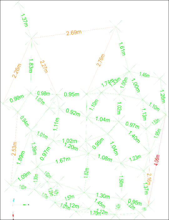
Note: Every point is the base of a rock bolt and every line is an edge between rock bolts. These lines will be recorded in the report as distances between the rock bolts.
Inconsistencies will appear as either incomplete triangulations or overlapping or conflicting edge network groups.
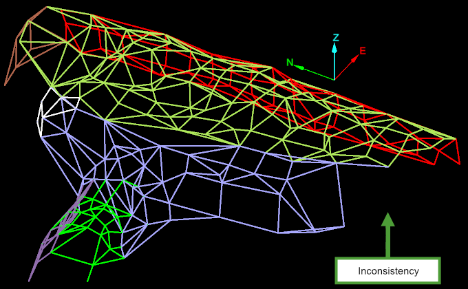
An inconsistency in the edge network appearing as an incomplete triangulation.
-
Fixing inconsistencies
-
To fix incomplete triangulations, follow these steps:
-
On the Edit tab, in the Primitives group, click
 Add Points.
 -
Enable Points type snap mode (on the right-hand side of the status bar) by clicking the
 (Snap Targets) option button followed by the
  (Angle from grid) snapping mode.
 -
Select the base of a rock bolt as the first point of the repair.
-
Select the base of a second rock bolt as the second point of the repair to create an edge between the two points. This edge will complete the triangulation.
-
Select additional bolt bases until the inconsistency has been filled in.
-
Repeat steps 1–5 for any other inconsistencies.
-
Right-click to finish.
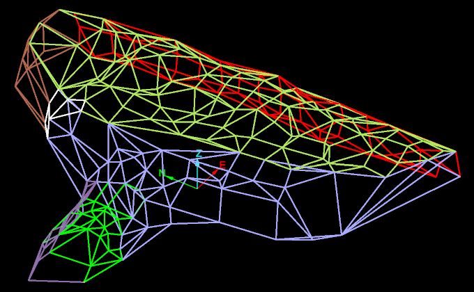
The above example shows all incomplete triangulations have been filled in.
-
Tip: To remove overlap or conflict between groups, select a redundant edge and press Delete. Repeat until done.
Finishing the report
Once inconsistencies have been fixed you can complete the report.
-
Click Next > in the Review bolt groups panel to Review report images. The Review report images panel opens with options to edit the images. Editing is done using the Windows default image editor. Images can be reset following an edit.
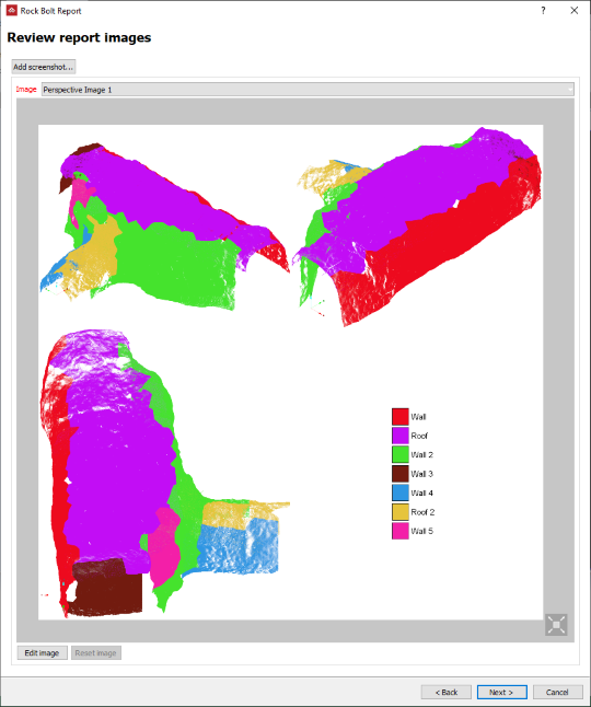
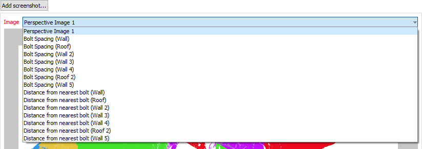
The Image drop-down list contains all the available images for review.
Example of the image of the Bolt Spacing (Roof 2)
- Click Next > on the Review report image panel to Preview report.
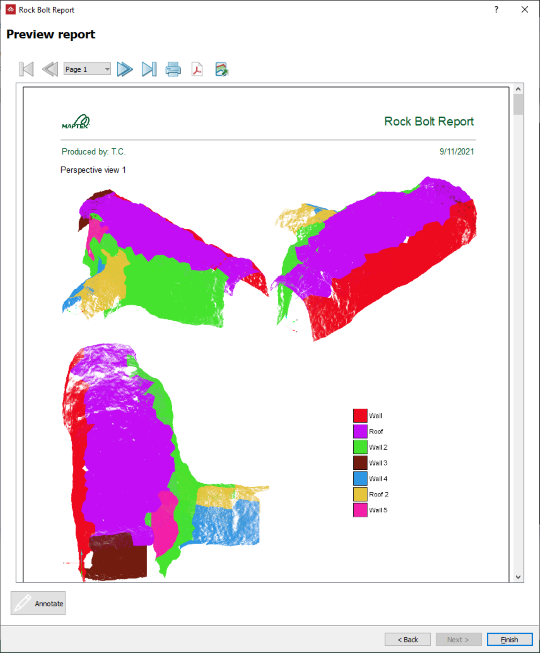
-
Click < Back to make any further changes.
-
Click Annotate to add comments to each section of the report before publishing.
-
Click the
 button to print the report.
-
Click the
 button to save the report as a PDF.
-
Click the
 button to save the report as a CSV or text file.
 -
Click Finish when done.
