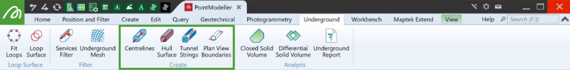
Create
Source file: create-group.htm
The Create group provides tools for advanced tunnel modelling, best applied after creating surfaces and filtering services and mesh.
|
|
Centrelines Generate centrelines for an underground tunnel network. |
|
|
Hull Surface Create a surface from only the points that make up the hull. |
|
|
Tunnel Strings Create 3D tunnel strings along tunnel points or surfaces. |
|
|
Plan View Boundaries Create a 2D outline of a 3D tunnel system. |
Centrelines
The Centrelines tool calculates and draws tunnel centrelines, and saves them for later review.
Because the Services Filter, Hull Surfaces and Tunnel Strings tools can also determine centrelines, it is not necessary to run this tool to complete your tunnel model. However, it is good practice to run the tool for the following reasons:
-
You can review and adjust centrelines before running the other tools for better results. To adjust centrelines, use the line editing tools on the Edit tab.
-
You can save processing time with the other tools by not regenerating centrelines.
-
You will have a permanent record of the centrelines.
-
To draw tunnel centrelines, on the Underground tab, in the Create group, click
 Centrelines, then follow the steps below.
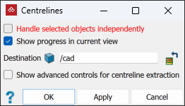
-
Select subject point clouds


 in either the project explorer or the active view window.
 -
Check or uncheck the following options per your requirements:
-
If Handle input objects independently is checked, the tool will create separate centrelines for each selected point cloud. Otherwise one set of centrelines will be created from the combination of all selected point clouds.
Note: When this option is unchecked, the tool treats all input point clouds as one, enabling better detection of centrelines. The results will usually be best with this option unchecked. If the results are unsatisfactory, try again with this option checked.
-
If you check Show progress in current view, centrelines will be loaded and displayed in the active view window as they are being created. This will help you to adjust the advanced parameters for a second run. If Show progress in current view is cleared, centrelines will only appear in the project explorer.
-
-
Change the output destination container as required.
-
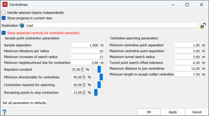
If necessary, select Show advanced controls for centreline extraction to adjust the centreline detection parameters. Do this particularly if results from the default parameters are unsatisfactory.
Note: Parameters are explained in mouse-over tool tips.
-
Click OK or Apply.
-
The centrelines will be created and nested inside the container specified (scrapbook by default).
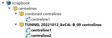
When Handle input objects independently is checked, names given to the centreline containers are derived from the individual input point cloud names.
Note: The number of centrelines created depends on the complexity of the input point clouds.
Tip: Each centreline in a result will be output as a single string. You can combine all resulting centre lines into one object using Edit > Object > Merge.
Hull Surface
The Hull Surface tool combines the Services Filter and Poisson Surface tools to generate a tunnel surface.
-
To create hull surfaces, on the Underground tab, in the Create group, click on
 Hull Surface, then follow the procedure below.
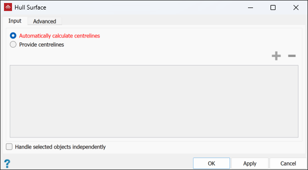
-
Select the tunnel data in the project explorer or active view window.
-
If required, check Handle objects independently. In this case, the tool will generate a separate hull surface from each input point cloud.
Note: As with the Centrelines and Services Filter tools, the best results are usually achieved if this is unchecked.
- Run the centrelines tool and ensure the centrelines are satisfactory. See Centrelines.
- Draw custom-made centrelines with the
 Line tool. See Lines.
 - Select the Advanced tab to modify the services filter Settings. Do this particularly if you're not satisfied with results from the default settings.
-
Click OK or Apply.
TipIf results are unsatisfactory, try either of the following:
After that, run this tool again using Provide centrelines.
Note: Parameters are explained in mouse-over tool tips.
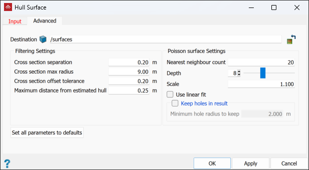
Tip: You can also change the output destination in the Advanced tab.
-
The hull surfaces will be created and nested inside the container specified in the Destination field on the Advanced tab (scrapbook by default).
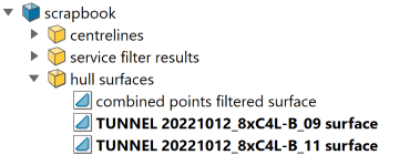
When Handle input objects independently is checked, names given to the hull surface containers are derived from the input point cloud names.
If the results are unsatisfactory, try the following:
- Run the services filter alone, using the same advanced filtering settings and data.
- Run the
 Poisson Surface tool on the filtered data with the same Poisson surface settings.
This could help to identify where to adjust settings for a better result.
Tunnel Strings
The Tunnel Strings tool generates the following strings to delineate tunnel floors, walls and ceilings:
-
floor strings
-
side wall strings
-
back strings
-
centre floor strings
-
centre back strings
-
rib strings (optional)
The tool can create tunnel strings from either point clouds or surfaces.
-
To create tunnel strings, on the Underground tab, in the Create group, click on the
 Tunnel Strings button, then follow the steps below.
-
Select the required objects in the project explorer or active view window.
-
This tool requires defined centrelines. It can either calculate them, or use existing ones. Select either Automatically calculate centrelines or Provide centrelines. If selecting Provide centrelines, add the centrelines by selecting them in the project explorer.
Note: If you select Automatically calculate centrelines, centrelines are only calculated for the purposes of services filtering; no centreline objects are created.
TipIf results are unsatisfactory, try either of the following:
- Run the centrelines tool and ensure the centrelines are satisfactory. See Centrelines.
- Draw custom-made centrelines with the Line tool. See Lines.
After that, run this tool again using Provide centrelines.
- Select the Advanced tab to modify the tunnel strings Settings. Do this particularly if you're not satisfied with results from the default settings.
Tip: You can also change the output destination in the Advanced tab.
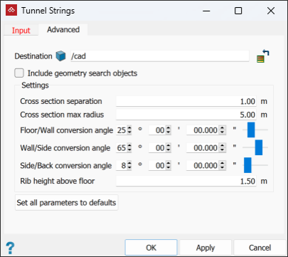
Note: Parameters are explained in mouse-over tool tips.
-
Select Include geometry search objects if you need to analyse ow the resulting tunnel strings were determined.
-
Click OK or Apply.
-
The tunnel strings will be created and nested inside the container specified in the Advanced tab (scrapbook by default).
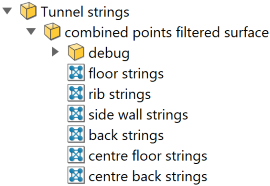
If you selected Include geometry search objects, geometry outputs will be placed in a sub-container named search geometry inside the tunnel strings output container.
Plan View Boundaries
The Plan View Boundaries tool creates the tunnel outline as an edge network ![]() , projected onto a horizontal plane.
, projected onto a horizontal plane.
-
To create an outline, on the Underground tab, in the Create group, click
 Plan View Boundaries, then follow the steps below.
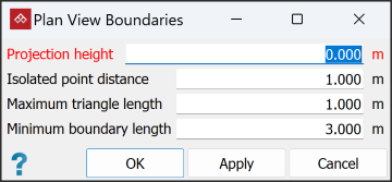
Note: Parameters are explained in mouse-over tool tips.
-
Select the relevant tunnel point clouds
or hull surfaces 
 in the project explorer or active view window.
 -
Enter the plane's height by either typing in the Projection height field or clicking a point at the required level in the view window.
Tip: You can use the action plane and snap modes to help with this. See Action Plane and Snap Modes.
-
Set the distance and length parameters according to requirements:
-
Isolated point distance: Points will be excluded if they are farther than this distance from any neighbouring points. Increase this value to include more points.
-
Maximum triangle length: Triangles with longer edges than this value are excluded from calculations. Increase this value if no boundary is made or the process takes too long.
-
Minimum boundary length: Produces a smoother outline and removes small 'islands' from the result.
-
-
Click OK or Apply.
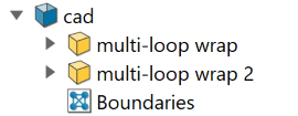
A new edge network object named Boundaries <number> will be created and nested in the cad container.