Primitives
Source file: primitives-group.htm
The Primitives group tools enable you to modify objects by moving, adding or removing points or facets.

|
|
Insert Points Insert additional points in a line segment. |
|
|
Add Points Add points to extend an edge. |
|
|
Move Points Change location of points. |
|
|
Reverse Facet Normals View and edit the orientations of facet normals. |
|
|
Add Facets Insert facets (triangles) in a surface. |
|
|
Extend Surface Add facets to a surface edge. |
|
|
Subdivide Surface Subdivide facets of a surface until all are smaller than a specified limit. |
Insert Points
The Insert points tool enables you to insert points along a line segment, effectively dividing it into new segments. The existing line segment can be part of a line, a polygon, a circle, or any other compatible object.
To insert points:
-
On the Edit tab, in the Primitives group, click
 Insert Points.
The status bar will display the Pick an edge to replace message.
-
Pick the point to insert from in the view window.
The digitisation tool then requests a location for the new point.
-
Pick the location for the new point, or enter coordinates and click
 (Accept content) in
the status bar.
(Accept content) in
the status bar.
The tool resets, ready for adding another point from the last point. -
Right-click anywhere in the view window, or click
 (Complete) in the status bar to complete the operation and exit the tool.
Press Esc or click (Cancel) in the status bar to exit the tool and discard changes.
Tip: Use the action plane and snap modes to simplify accurate point selection. See Action Plane and Snap Modes.
|

|
|
Inserting new points. |
Two new points inserted. |
Add Points
The Add Points tool enables you to add new points and connect them to existing points. The existing points can be part of a line, a shape, or any other compatible object.
To add points:
-
On the Edit tab, in the Primitives group, click
 Add Points.
The status bar will display the Pick point to add from message.

-
Pick a starting point on a CAD object in the view window from which to add new points.
-
Pick the location of the new point, or enter coordinates in the digitisation request and click
(Accept content) or press Enter.
-
Repeat step 3 to add more points, as required.
-
Right-click anywhere in the view window, or click
(Complete) in the status bar to complete the operation and exit the tool.
Press Esc or click (Cancel) in the status bar to exit the tool and discard changes.
Tip: Use the action plane and snap modes to simplify accurate point selection. See Action Plane and Snap Modes.
|
|
|
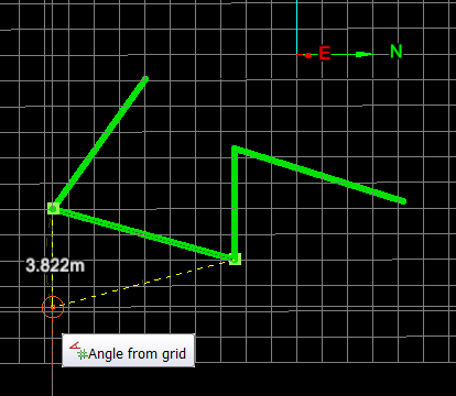
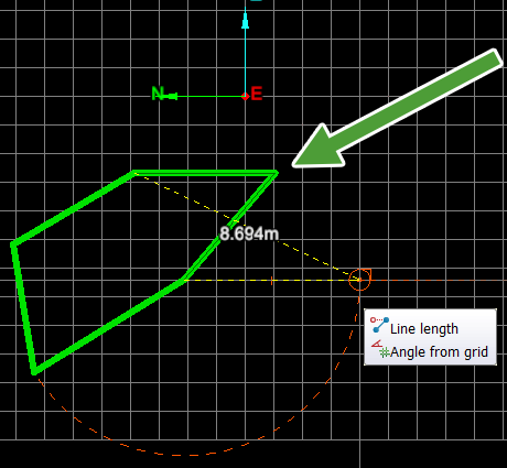
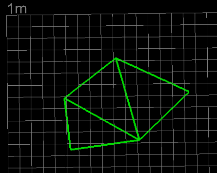
Adding points to a polygon. |
New points added. |
Move Points
The Move points tool enables you to move an existing point to a new location. The point can be part of a line, polygon, circle, surface, or any other compatible object.
To move points:
-
On the Edit tab, in the Primitives group, click
 Move Points.
The status bar will display the Pick point to move message.
-
Pick the point to move in the view window. The digitisation tool requests a new location.

-
Pick the new location or enter coordinates in the digitisation tool. The point is placed at the new location and the tool is reset and ready to pick another point.
-
To exit the tool when finished right-click or click
(Complete) in the status bar.To exit without completing the operation, press Esc or click
(Cancel) in the status bar. Note: You can also right-click to exit before picking a new point location.
-
Right-click anywhere in the view window, or click
(Complete) in the status bar to complete the operation and exit the tool.
Press Esc or click (Cancel) in the status bar to exit the tool and discard changes.
Tip: Use the action plane and snap modes to simplify accurate point selection. See Action Plane and Snap Modes.
|
|
|
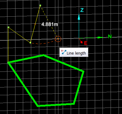
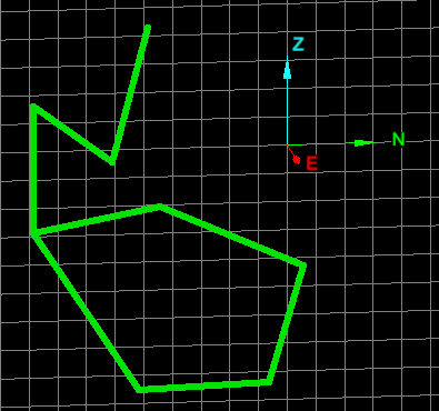
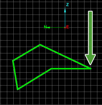
Moving a point in a polygon. |
Point move completed. |
|
|
|
Moving a point in a surface. |
Reverse Facet Normals
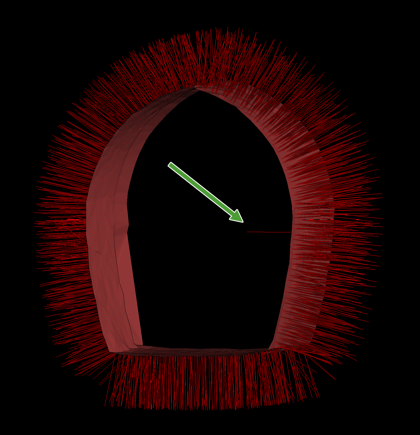
3D programs need to keep track of which side of a facet that the normals are pointing. Some facets may be incorrectly formed when a model is built or modified, resulting in the normals being on the wrong side. Thus, problems can occur when operating on facets or displaying surfaces.
The Reverse Facet Normals tool enables you to manually reverse the directions of wrongly oriented normals.
Reverse facet normals as follows:
-
Select the surface with facet normals to be reversed.
-
On the Edit tab, in the Primitives group, click
 Reverse Facet Normals.
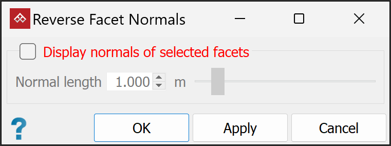
-
Select Display normals of selected facets to see the facet normals represented by lines emanating from the facet centres. With a whole surface selected, all facet normals are shown. You can adjust the length of these representative lines with the Normal length slider or text box.
-
Identify and pick only the facets with normals to be reversed.
Note: As soon as you pick one facet, all other normals will disappear from view. You might need to reverse normals one at a time.
-
Click OK to run the operation and close the tool, or Apply to run the operation and repeat.
Important: If you clicked Apply, close the tool by clicking Cancel. If you click OK with facets selected, the operation will run again, returning the selected normals to their original orientations.
|
|
|
A tunnel surface where facet normals are supposed to point outwards, but one facet normal points inwards, indicated by the arrow. |
Add Facets
The Add facets tool enables you to add extra facets to a surface. Each facet is made up of three vertices (points). The new facets can be directly attached (sharing a side) or not attached to the existing surface.
Add facets as follows:
-
Set the surface render mode to Wireframe to see the facets of a surface more clearly. See Effects > Surface render mode.
-
On the Edit tab, in the Primitives group, click
 Add facets.
 -
Select a surface

 to add extra facets
to.
to add extra facets
to. -
Pick a point to start defining the new facet, then pick two more points to complete the facet.
Tip: Turn on snap modes to aid with point picking.
-
Repeat step 4 to make more facets.
-
Right-click anywhere in the view window, or click
(Complete) in the status bar to complete the operation and exit the tool.
Press Esc or click (Cancel) in the status bar to exit the tool and discard changes.
|
|
|
|
Select wireframe mode to view facets clearly. |
Select surface and add facet. |
Finished surface with two extra facets displayed in smooth shaded surface mode. |
Extend Surface
The Extend Surface tool allows you to add new facets to the edge of a surface by defining new points as outer corners of new facets. A new facet is made up of three vertices (points) and one or two borders that are shared with other facets of the surface.
To extend a surface:
-
Set the surface render mode to Wireframe to see the facets of a surface more clearly. See Effects > Surface render mode.
-
On the Edit tab, in the Primitives group, click
 Extend surface.
 -
Select a surface
needing extra facets
. -
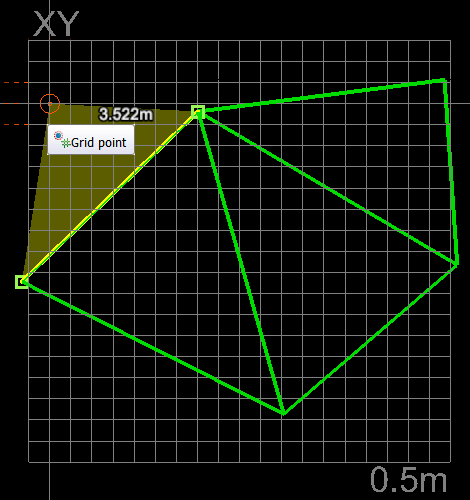
Pick an existing line segment of the surface to start defining the new facet, then pick a new point to complete the facet.
-
Repeat step 4 to make more facets.
-
Right-click anywhere in the view window, or click
(Complete) in the status bar to complete the operation and exit the tool.
Press Esc or click (Cancel) in the status bar to exit the tool and discard changes.
|
|
|
|
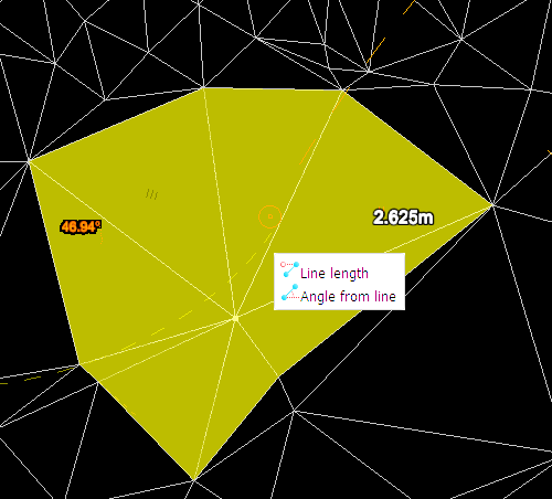
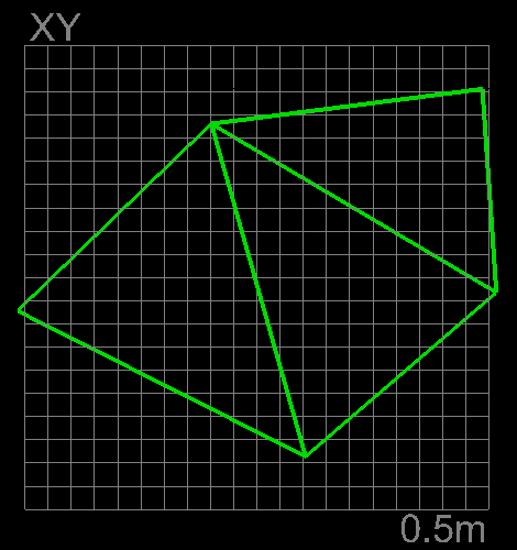
Select wireframe mode to view facets clearly. |
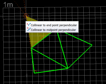
Select surface boundary (line segment) first, then add external point for new facet. |
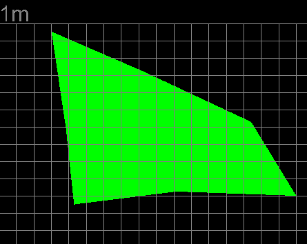
Finished surface example with an extra facet and displayed in smooth shaded surface mode. |
Subdivide Surface
The Subdivide Surface tool allows you to divide pre-existing surfaces into smaller triangles. You can define the size of the subdivisions by entering an appropriate edge length. PointModeller will then re calculate and redraw the surfaces with new divisions.
Subdivide a surface as follows:
-
Set the surface render mode to Wireframe to see the facets of a surface more clearly. See Effects > Surface render mode.
-
On the Edit tab, in the Primitives group, click
 Subdivide Surface.
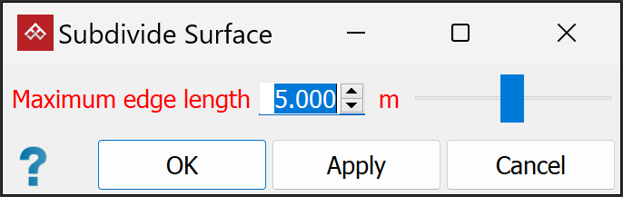
-
Select the surface
to subdivide. -
Enter a Maximum edge length to set the subdivided triangle size limit.
-
Click OK or Apply.
Note: The surface shape won't change but triangles will be subdivided.
|
|
|
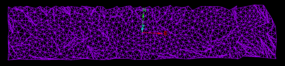
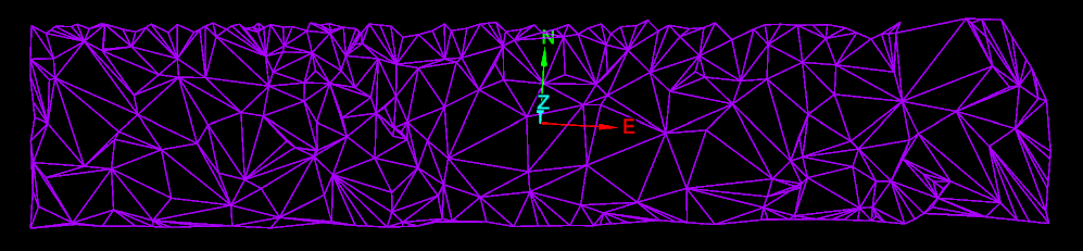
Surface viewed in wireframe before it is subdivided. |
|
|
|
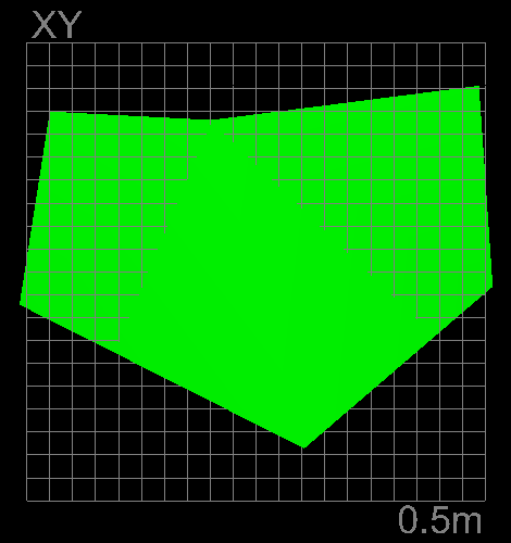
Surface viewed in wireframe after it has been subdivided. |