To simplify a surface by distance error
The Simplify tools allows surfaces to have their facet count reduced, while retaining the overall shape. This option works on a selection of facets that can be an entire surface, a group of surfaces or a selection of facet primitives on a surface. Surfaces may also require simplification in order to export them to packages that are unable to import or display surfaces with a large file size.
This option provides a method
of limiting the surface deviation caused by triangle simplification.
Simplify a surface by an allowable distance error by the following:
-
Select the surface in the project explorer.
-
On the Edit ribbon tab navigate to the Surface group. From the Simplify drop-down list select
 Simplify by
Distance Error.
Simplify by
Distance Error.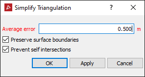
- Enter the maximum allowable Average error by which the simplified surface can deviate from the original surface.
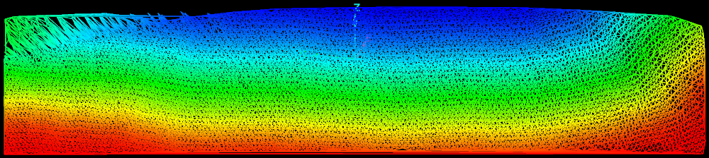
The Average error is the average distance from the original surface, thus there will be some areas of the new surface that are further away from the original surface than the average error. An example is shown below.
- Select Preserve surface boundaries to leave the boundary unchanged.
- Select Prevent self intersection to disallow line intersections, however the analysis to guarantee the intersections don't occur will slow the simplification down.
-
Click OK or Apply.
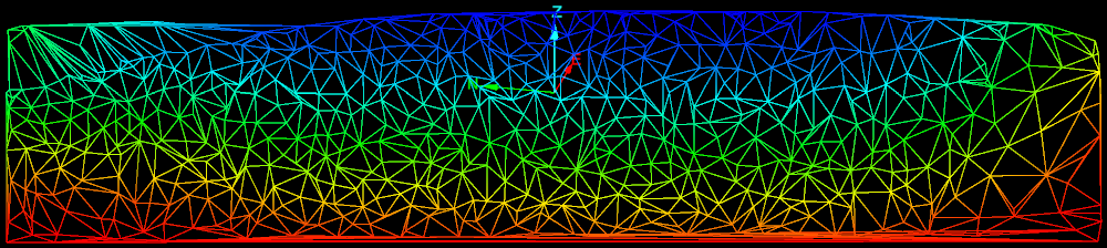
The simplification process will amalgamate the triangles in flat regions first, preserving edges and other curved areas. It will also simplify triangles around the boundary of the triangle selection.
Note: The simplification can introduce inconsistencies in the surface, such as triangles that overlap or cross. Follow the steps below to check for and fix inconsistencies.
The following can be done to check for inconsistencies.
-
On the Query ribbon tab navigate to the Surface group and select
 Surface Validity.
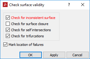
-
Untick Check for surface closure. This option is only used for closed solids.
-
Select Mark location of failures to create objects in the cad container that highlight the locations of the errors.
-
Click OK.
-
Drag and drop the object(s) created in the cad container onto the surface View window to display any errors found.
-
To repair any errors found, zoom into the error and select surface render mode in wireframe
 .
.
-
Using point selection mode, select a corner point on the triangle and clickDELETE on the keyboard.
-
To fill the hole created, on the Edit ribbon tab navigate to the Fix group and select
 Fill
Holes.
Fill
Holes. -
Repeat this procedure for all errors found.
Example of an error