To translate data
Use this option
to translate (shift) data in a straight line in any direction by using
one of the following methods:
- Two points.
- Two points and distance.
- Facet and distance (the translate direction will be perpendicular to the selected facet).
- Axis aligned (parallel to an axis) and distance.
- Bearing, inclination and distance.
Direction vector guide
The direction vector is a visual aid
for these methods and is drawn as an arrow representing the direction
and distance to be translated. It is defined and used in the Two
point methods and may
be used in the axis aligned or
bearing/inclination methods. If
not used in the axis aligned or
bearing/inclination methods, there
is no visual guide for translation direction and distance. It is not used
in the Facet and distance method,
however, this method produces its own direction vector as a visual guide.
![]()
The following
table summarises the relationships between the Two
point methods' direction vector
and the other translation methods.
| Translation method | Two points - Direction vector shown as guide for translation. |
|---|---|
|
Two points |
Required, enter values or click at two points. |
|
Two points and distance |
Required, enter values or click at two points. |
|
Facet and distance |
Not used. This method produces its own direction vector as a guide. |
|
Axis aligned and distance |
|
|
Bearing, inclination and distance |
|
Translate forward / backward
Once the direction and distance have been nominated by one of the translation methods, you click Translate forward to perform the translation process. Use Transform backward to retrace the path back to the start position.
Translate a copy
This option allows you to produce a copy of the selected data/object(s) located at the nominated direction and distance from the source.
General procedure:
-
On the Edit ribbon tab navigate to the Transform group and select
 Translate
OR in the Position and Filter ribbon tab navigate to the Transform group and select
Translate.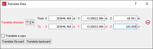
-
Select a Translate direction method (the options are listed above).
Depending on your choice, you can specify two points for a direction (From and To), a distance length, facet (normal) direction, axis or bearing and inclination components.
Enter values manually into the entry boxes, or click in them and then at the desired location in the View window, or adjust sliders where appropriate.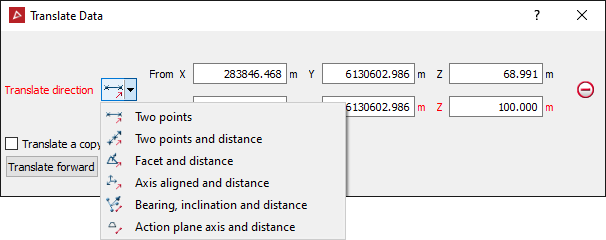
- If using the Two points variations, click on the point or feature that you want to translate, and then on the point to translate to.
Tip: Right-clicking on Translate direction, From or To will display a context menu.
The
coordinates of these points will be loaded into the From
and To fields.
-
Select the data / object to be translated in the project explorer and make sure that no other objects are highlighted.
-
Click the Translate forward or Translate backward buttons to translate (as applicable).
Select Translate
a copyto duplicate the original
object and translate the new copy each time Translate
forward or Translate Backwards is selected.