Importing data
To import other supported data types
To import custom text file formats
To import Maptek object data
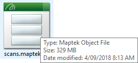
.maptekobj is the Maptek object file. The purpose of this generic file format is to allow the operator to transfer objects between other projects, or any arbitrary groups of objects excluding external referenced files. All data can be stored in one file, which makes it easier to email than Maptek projects.
-
On the Home ribbon tab navigate to the Data group and click
 Import.
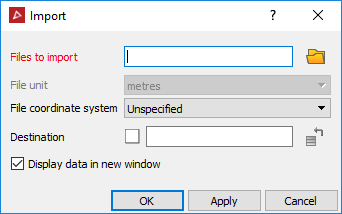
To auto import scan files
To import new scan files:
-
Remove the USB memory stick from the scanner controller.
-
In PointStudio create a new project, or open an existing one.
-
Insert the USB memory stick containing the scans into the PC.
The program recognises the files and will automatically launch the scan import tool. To import scan files in other formats refer to Import other supported data types.
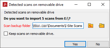
- Change the location of the scan backup folder if required. The default location displayed is the location of the project.
Checking Keep scans on removable drive will keep the original data on the USB memory stick, otherwise they will be removed.
- Click Yes. The scans will be imported into the open project and a backup copy created. Scans will be placed into folders according to the date they were acquired.
Maptek Drive scan files
Maptek
Drive scan files include the 'Track'
data which represents the path driven during the driving scanning process.
This path is effectively the origin of scanning as it progresses around
the driven path. The Track data
can be extracted from the main scan file and saved in the CAD
container as a 3D line, by using the Query
> ![]() Scan Extents command. The Track object uses the original scan
data name and will be appended with '_Track'.
It is a separate object that can be moved and rotated, etc. on its
own - the associated scan data will remain unchanged.
Scan Extents command. The Track object uses the original scan
data name and will be appended with '_Track'.
It is a separate object that can be moved and rotated, etc. on its
own - the associated scan data will remain unchanged.
The Track object can be used:
- To apply transformations to custom coordinate systems, then apply the same transformations to the scan data to position and orient the data correctly.
- As a guide for other transformations, as it represents the driving origin of all scan data and gives a simplified guide/visualisation to the transformation.
- As a reference object for filtering scan data, eg. data within a certain distance of the Track path.
To import survey points
Survey reference
stations are imported from a comma-separated text file (.txt,
.csv). The
file should be in the format Easting, Northing, Elevation, Name (X, Y,
Z, label OR index, X, Y, Z, label).
When you select
a text file for import, you will be prompted to identify the type of data
in the file. Text files can contain many different types of data in various
formats. If the format matches the requirement above, you can select Survey Points from the list. If
the format does not match, refer to Import
custom text file formats.
- On the
Home ribbon tab navigate to the Data group and click Import.
Tip: Double-clicking on the workspace also opens the Import panel.
-
Click the folder icon
 to browse
to the data location.
to browse
to the data location. -
Select the files to be imported. The data will be placed in the survey container.
To import other supported data types
Many data types can be imported. The file import panel allows you to select the type of file you desire and it will provide appropriate options for importing. Apart from the filename and destination, you may have the option to nominate a coordinate system for the file. Refer also to File > Preferences for a default setting option applicable to coordinate systems on import.
-
On the Home ribbon tab navigate to the Data group and click
Import.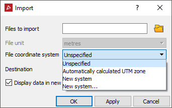
Supported data types are shown below:
Note: AutoCAD files are in the 2009 format specification.
Note: .txt files must be in one of the following formats (if not, see Import custom text file formats):
- Scan text file: Space delimited for scan files with the format (X Y Z Red Green Blue Intensity)
- Point text files: Comma delimited for all regular object types with the format (X, Y, Z, Red, Green, Blue). Not available for text or construction plane objects.
- Survey
point text files: Comma delimited file with the format (X, Y, Z, label
OR index, X, Y, Z, label).
To import any supported data types:
-
On the Home ribbon tab navigate to the Data group and click
Import. -
Click the folder icon
to browse
to the data location.
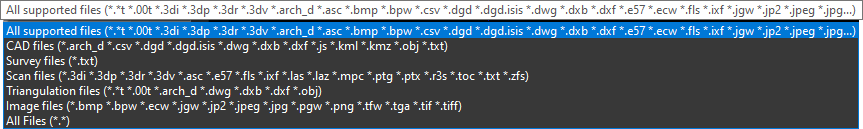
Click All Supported Files to see allowable file types.
- Select the files to be imported.
Note: Only one type of file can be imported at a time.
Tip: You can drag and drop files directly from Windows Explorer. Dropping the files in the workspace will place the data in the appropriate container.
Importing data brings a copy of the original file into your project. Altering the file will not modify the original data.
To import custom text file formats
Predefined PointStudio text file formats:
- Scan text file: Space delimited for scan files with the format (X Y Z Red Green Blue Intensity)
- Point text files: Comma delimited for all regular object types with the format (X, Y, Z, Red, Green, Blue). Not available for text or construction plane objects.
- Survey
point text files: Comma delimited file with the format (X, Y, Z, label
OR index, X, Y, Z, label).
To import a text file (ASCII file) that is not in one of the predefined formats listed above, use the custom text file import method below:
-
On the Home ribbon tab navigate to the Data group and click
Import. -
Click the folder icon to browse to the data location.
-
Select the ASCII or text files to be imported.
-
Click Open. The Select value dialog displays.
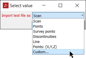
-
Select from standard data arrangements which have been predefined.
-
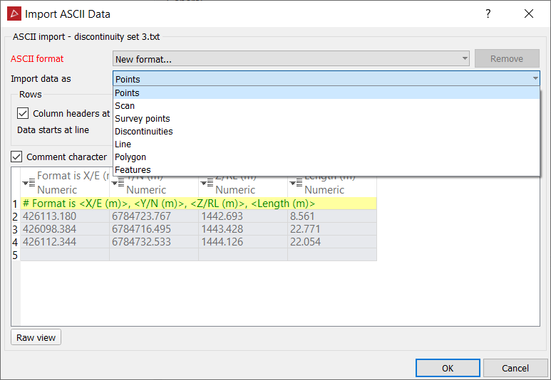
Next select to import the data as:
-
Otherwise select Custom from the drop-down menu. The New Format options display.
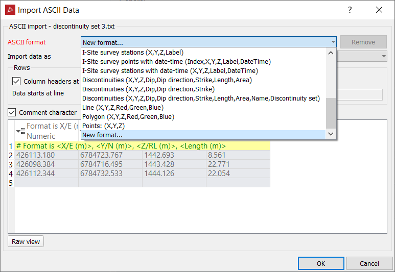
-
Define the data type to be imported. Different data types can have different attributes:
- Points: Must include X, Y coordinates. May include Z and colour RGB data.
- Scan: Must include X, Y coordinates. May include Z, colour RGB and intensity data.
- Survey points: Must include X, Y coordinates and label. May include Z, an index and date-time.
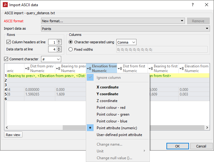
- Ensure the Columns displays the correct options for data line arrangement.
The Comment character defines the character used in the file to determine text that is a comment.
- If the Custom format is likely to be used frequently, type a meaningful name in the ASCII format name field.
The next time data is imported, the defined name will appear as an option in the Select value window.
Tip: Formats that are no longer required can be deleted by selecting the format from the drop-down list and clicking Remove.
To import image files
Image files can be imported and exported in association with surfaces and scans. The images can be draped over the entire target object or placed on a specific patch. Appropriate options will be available dependent on the target object for the image.
Note:
This allows a panorama photograph from a scan to be exported, edited,
then imported to replace the original image.
-
On the Home ribbon tab navigate to the Data group and click
Import. -
Select an image file to import ( .bmp, .jpeg, .jpg, .png, .tif, .tiff)
-
The default destination in the images container is automatically selected.
-
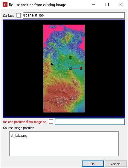
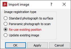
Select whether the image is of a section of a scene to be stitched onto a surface (Standard photograph to surface) or a full panoramic image that extends around a scene (Panoramic photograph to scan). Otherwise re-use an existing position on an object, or replace on an existing position and then adjust/update.
- For
applying the image to an object, enter the object's name or click
and drag the object to the Destination window. The image will be superimposed
on the object. The image can be orientated using a basic Two-point
method which is intended for applying flat images to flat regions
on surfaces. Otherwise, Multi-point
is intended to apply a photographic image onto a 3D scene component.
It uses an algorithm that models a camera lens and attempts to determine
the distance and orientation of the camera within the scene.
Refer to How do I? > Apply image to object for attaching and positioning an image on an object, using either Two-point or Multi-point methods.
For importing an image into an existing position or updating an existing image, the panel below will open and allow you to complete the relevant details.