Toes and Crests (Actual and Ideal)
Source file: actual-toes-and-crests.htm
Create
toes and crests is used to generate actual and/or ideal toe and
crest lines from an initial set of preliminary
toe and crest lines.
-
On the Create ribbon tab, go to the Topology group. From the Toes and Crest drop-down list select
 Actual and Ideal.
-
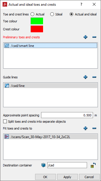
Select one of the Toe and crest lines options:
- Actual: Generates lines that share points along the preliminary toe and crest edges, fitting the original data. Lines created are regularly sampled such that they have an approximate point spacing of the value specified on the dialog box.
-
Ideal: Generates lines that better fit the surface. The toe lines will be pushed in, under the rill, towards where the ideal toe lines should be if a batter was just cut. Similarly, the crest lines will be pulled out, towards where the ideal crest lines would be if parts of the batter had not fallen down creating the rill. The pit can be a triangulation, a point set or a scan. This option will perform better on objects with higher point densities.
-
Actual and Ideal: Generates both actual and ideal toe and crest lines as above.
-
Drag the recommended container (see Toes and Crests (Preliminary)) into the Preliminary toes and crests field.
-
Guide lines can be added to assist in the toe and crest classification of actual and ideal lines. These guide lines are also used to assist in the fitting of ideal toes and crests. Guide lines can be any lines, usually created with the
 Draw Line
tool. These lines should be used to define creases and bends in the
surface to generate better fitting ideal toe and crest lines.
 -
Enter the Approximate point spacing to define the level of detail to be applied to the lines.
-
Clear the Split toes and crests into separate objects checkbox to create the toes and crests as a single object. Leave selected to create separate objects.
-
Drag the data to fit the toes and crests to into the Fit toes and crests to field.
A new container named actual or ideal is created inside the cad container named after the triangulation.

Actual toes and crests (left) and ideal toes and crests (right). Crests are red and toes are green.
