Grid
Source file: create-a-grid.htm
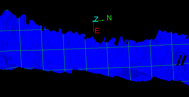
Use the Grid tool to fit a grid pattern to a surface. You can generate a grid pattern in either of the following ways:
-
As points, which is useful for creating spot heights.
-
As lines, to create a gridded surface at a defined spacing and alignment.
-
On the Create ribbon tab, go to the Create group and select
 Grid.
Grid.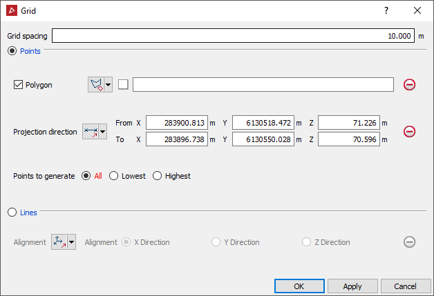
-
Enter the desired Grid spacing.
-
Select Points or Lines for the grid.
 Expand if you selected Points
-
If required, select Polygon and create a polygon around the area that requires a grid. There are two ways of drawing a polygon for this tool. Do one of the following:
-
Select
 By Polygon then create a polygon using the
  Polygon tool and select it to populate the Polygon field.
 -
Select
 By Points then create a polygon by selecting points in the view window or entering coordinates in the Grid tool panel. The polygon will be completed when you click Apply or OK.
If you leave Polygon unselected, points will be generated to cover the entire object.
-
-
Adjust the Projection direction if required.
 Two points: Define the direction by specifying two points.
 Facet: Make the direction perpendicular
to a selected facet.
 Axis aligned: Define the direction by an axis of the view window.
 Bearing and inclination: Define the direction by a bearing and inclination angles.
 Action plane axis: Define the direction by an axis of the action plane.
-
 Polygon best-fit plane normal: Define the direction as the normal to a plane-of-best-fit to a polygon.
-
Select whether to generate All points fitted to the surface, the Lowest points, or the Highest points.
-
Highlight the triangulation (surface to fit the gridded points) in the project explorer.
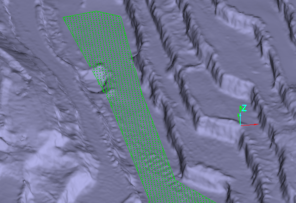
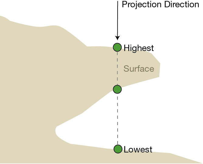
The example below shows the highest and lowest points that would be selected if there is overhanging data. Selecting All will generate all three marked points.
 Expand if you selected Lines
-
Adjust the Alignment as required.
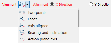
 Two points: Define the direction by specifying two points.
 Facet: Make the direction perpendicular
to a selected facet.
 Axis aligned: Define the direction by an axis of the view window.
 Bearing and inclination: Define the direction by a bearing and inclination angles.
 Action plane axis: Define the direction by an axis of the action plane.
Note: Only the X and Y components are used in creating the grid. The grid is always projected in the Z direction. If no X or Y alignment is provided, the grid will automatically align with the axes.
-
-
Click OK or Apply.
The grid is saved in the cad container.
