2D Polygon
Source file: 2d-polygon.htm
Polygons are
closed lines or loops used to define boundaries. Use polygons
to define areas of interest for modelling, filtering and cropping data.
The 2D polygon tool draws polygons on the action plane. The action plane assists in determining the polygon's placement in 3D
space. The resultant shape is saved in the cad  container. To create 3D polygons see Polygon.
Creating a 2D polygon
Create a 2D polygon as follows:
-
Set up the action plane where you want to place a polygon.
-
On the Create ribbon tab, go to the Draw group. From the Polygon drop-down list select
 2D Polygon.
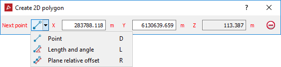
The panel will open, allowing manual input of coordinates for points. You can also select points in the view window.
-
Click in the view window to select the first point or enter values manually in the X, and Y input fields and press Enter. Click
 to clear the input fields.
Note: The Z field is disabled because the polygon is drawn in 2D.
The Next point drop-down will be enabled, from which you can select the coordinate entry mode as follows:
-
 Point - enter the next point's coordinates.
 -
 Length and angle - enter the length and compass direction of the next line segment.
 -
 Plane relative offset - enter the next point's distance from the last point in the X and Y directions.
-
-
Enter as many points as required to build a polygon using the preferred coordinate entry mode, or by clicking on the action plane.
The point coordinates, length and angle, or plane relative offset will be displayed as the polygon is being created.
-
Right-click to finish drawing the polygon.
If the polygon is incomplete, a line will be automatically created from the last point to the first point, closing the shape.
-
Press Esc or click
 to exit the function,
or continue creating new polygons.
to exit the function,
or continue creating new polygons.
Note: Once the shape is complete and the polygon tool is closed, the shape is no longer attached to the action plane. You can move it as required.
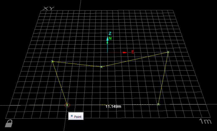
2D polygon creation. The next line segment's length is displayed according to the mouse's position.
Helpful shortcuts:
Use the following keyboard shortcuts for controlling the tool panel:
-
D to switch to Point entry mode
-
X to highlight the X field
-
Y to highlight the Y field
-
Z to highlight the Z field
-
-
L to switch to Length and angle mode, then:
-
L to highlight Length field
-
A to highlight Angle field
-
-
R switch to plane Relative offset mode (Action plane), then:
-
X to highlight Relative X field
-
Y to highlight Y field
-
-
Tab to step through the fields.
