Line
Source file: 3d-line.htm
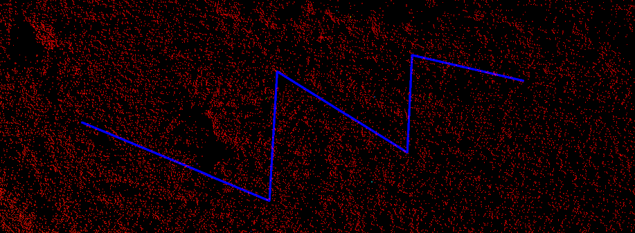
Lines can be created to manipulate or add to existing data. The resulting line will consist of one or more straight line segments between points that is specified in 3D space. To create 2D lines, use the command 2D line.
-
On the Create ribbon tab, go to the Draw group. From the Line drop-down list select
 Line.
Line.
A panel will open displaying the input fields for the First point.
-
Click in the view window to select a the First point or enter values manually in the X, Y and Z input fields. Click
 to clear the input fields.
The Next point drop-down will be enabled, from which you can select the coordinate entry mode as follows:
-
 Point - enter the next point's coordinates.
 -
 Length, bearing and inclination - enter the length, compass direction and inclination angle of the next line segment.
 -
 Relative offset - enter the next point's distance from the last point in the X, Y and Z directions.
-
-
Enter as many points as required to build a line using the preferred coordinate entry mode, or by clicking on the action plane.
-
Right-click to complete the line.
-
Repeat the above steps to create another line.
-
Press Esc or click
 to exit the function,
otherwise continue creating new edges of a line.
The line is saved in the cad![]() container.
container.
Tip: Create lines while in top view ![]() , or use snap modes to ensure the line is created in the intended location.
, or use snap modes to ensure the line is created in the intended location.

Helpful shortcuts:
|
D switch to point entry mode |
||
|
|
L switch to length, bearing and inclination mode, then:
|
|
|
R switch to relative offset mode (standard 3D axes), then:
|
||
