Rock Bolt Report
Source file: rock-bolt-analysis-rock-bolt-report.htm
Once all the rock bolts have been created and categorised by type, use Rock Bolt Report to generate a PDF report that visually and numerically summarises the distribution of rock bolts.
Preparing the data
Follow these steps to prepare the report data:
-
On the Query ribbon tab, go to the Rock Bolts group and select
 Rock Bolt Report. The Rock Bolts Report panel will open.
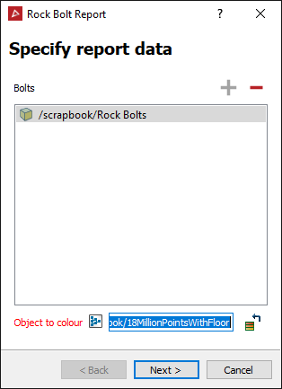
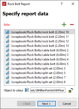
- Select the rock bolts created or select the whole Rock Bolts container and click
 .
. - Click in the Object to colour field then select the object to be used to generate screenshots indicating areas with problematic bolt spacing. This will most likely be a scan the bolts were created from.
- Click Next >.
- Select the rock bolts created or select the whole Rock Bolts container and click
-
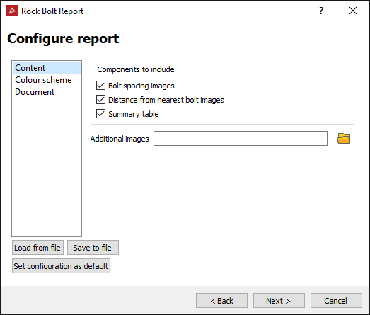
Configure report panel will open to adjust the look of the report and the data that will be displayed. Select the required options in the subsections as follows:
-
From the Content section, choose components to include.
- Bolt spacing images
- Images of the scan surface coloured by the distance from the nearest bolts
- Summary table
- Any Additional images relevant to the job
-
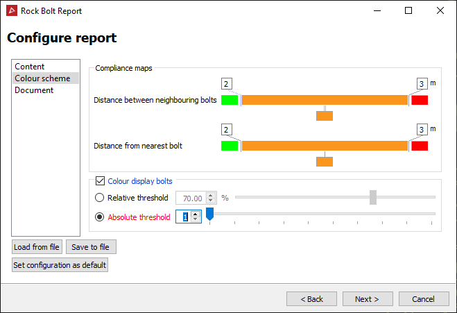
Set the Colour Scheme for the rock bolts and the cut-off distance between them.
-
Adjust the Compliance maps as required. See Modify a colour scale for detailed instructions.
- Select Colour display bolt to colour the bolt objects as well.
- Select Relative threshold to set the % of neighbouring bolts that fall beyond a colour boundary. Or
- Select Absolute threshold to give an explicit number of bolts instead of a percentage. For example, if a bolt is connected to 4 neighbouring bolts, one 0.5 m away, two 2.5 m away, and one 3.5 m away then, based on the Compliance maps above:
- An absolute threshold of 2 or 3 would cause that bolt to be coloured orange, because only one neighbour is ≥ the 3 m cut-off, but 3 of its neighbours are ≥ the 2 m cut-off.
- An absolute threshold of 1 would cause that bolt to be coloured red, because at least one of its neighbours is ≥ the 3 m cut-off.
- An absolute threshold of 4 would cause that bolt to be coloured green, because only 3 of its neighbours are ≥ the 2 m cut-off.
 Expand for detailed instructions
-
-
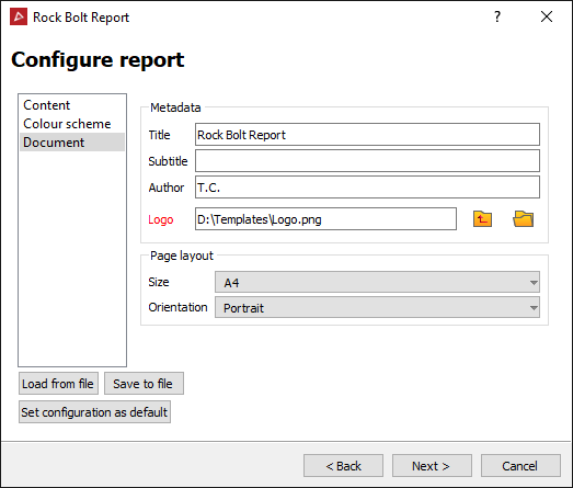
In the Document section, add any required metadata and set a page layout.
-
-
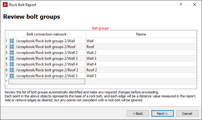
Click Next > to progress to reviewing the bolt groups. The Review bolt groups panel will open displaying the edge networks it has created, grouped by walls and roofs.
Note: Leave the Review bolt groups panel open.
-
Select the Rock bolt group container from the project explorer and load it in a new view window to find any inconsistencies. The rock bolt groups are displayed as edge networks. Each group will be coloured differently.
Note: You can save and recall report configurations to save time for future reports. Use the Load from file, Save to file and Set configuration as default buttons as required.
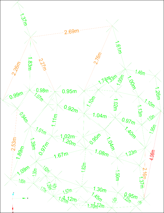
Note: Every point is the base of a rock bolt and every line is an edge between rock bolts. These lines will be recorded in the report as distances between the rock bolts.
Inconsistencies will appear as either incomplete triangulations or overlapping or conflicting edge network groups.
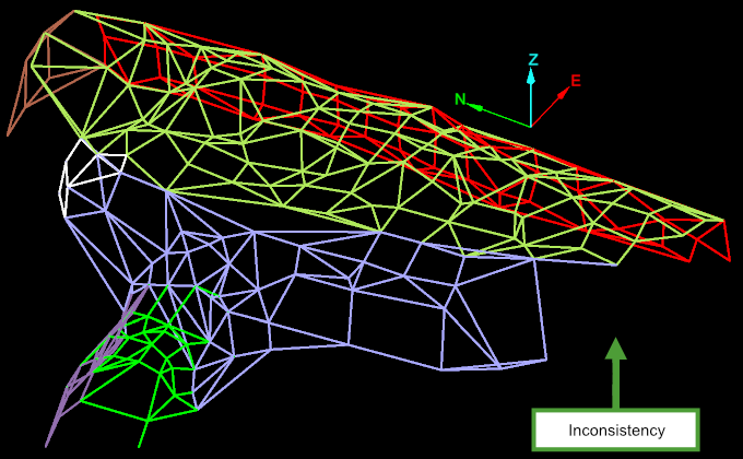
An inconsistency in the edge network appearing as an incomplete triangulation.
Fixing inconsistencies
Fix incomplete triangulations by adding as follows:
-
On the Edit ribbon tab, go to the Primitives group and select
 Add Points.
 -
Enable Points type snap mode (on the right-hand side of the status bar) by clicking the
 Snap Targets option button followed by the
  Angle from grid snapping mode.
 -
Select the base of a rock bolt as the first point of the repair.
-
Select the base of a second rock bolt as the second point of the repair to create an edge between the two points. This edge will complete the triangulation.
-
Select additional bolt bases until the inconsistency has been filled in.
-
Repeat steps 1-5 for any other inconsistencies.
-
Right-click to finish.
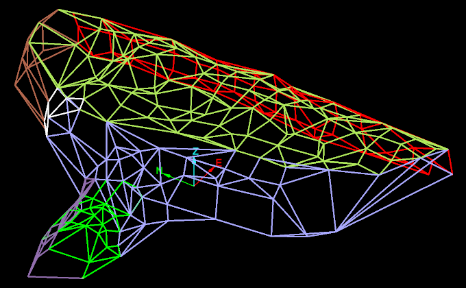
The above example shows all incomplete triangulations have been filled in.
- To remove overlap or conflict between groups, select a redundant edge, press Delete and repeat until done.
Finishing the report
Once inconsistencies have been fixed you can complete the report.
-
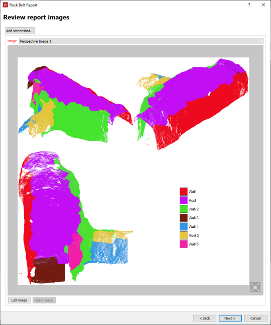
Click Next > in the Review bolt groups panel to Review report images. The Review report images panel opens with options to edit the images. Editing is done using the Windows default image editor. Images can be reset following an edit.
- Click Next > on the Review report image panel to Preview report.
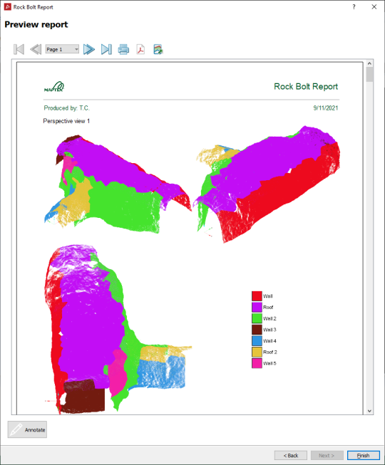
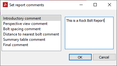
-
Click on Annotate to open the Set report comments panel and add comments.
-
You can now print the report or export it as either a PDF or a CSV file.
-
Click Finish when done.
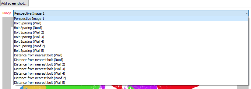
The Image drop down list contains all the available images for review.
Example of the image of the Bolt Spacing (Roof 2)
