Rock Bolts
Source file: rock-bolts-group.htm
Note: Rock Bolts is an add-on that requires additional licensing, which may be obtained via your Maptek Account portal. Please see Licensing Applications in the Workbench help for details.
The Rock Bolts group tools enable you to prepare and review rock bolt plans and generate reports.

|
|
Place Rock Bolt Manually place rock bolts. |
|
|
Rock Bolt Detection Automatically detect rock bolts in scans. |
|
|
Verify Bolts Verify detected and created bolts. |
|
|
Create Bolt Network Create loop or triangulation networks of rock bolts. |
|
|
Rock Bolt Report Generate a rock bolt report. |
Place Rock Bolt
The Place Rock Bolt tool enables you to place individual rock bolts that were missed in the automated process.
A scanner might miss a rock bolt because its line-of-sight is obstructed by other objects, a part of the wall, or protruding rock.
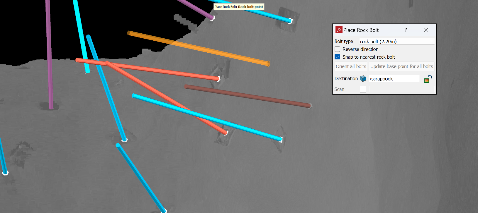
Adding rock bolts
To add a rock bolt ![]() :
:
-
On the Query tab, in the Rock Bolts group, click
 Place Rock Bolts.
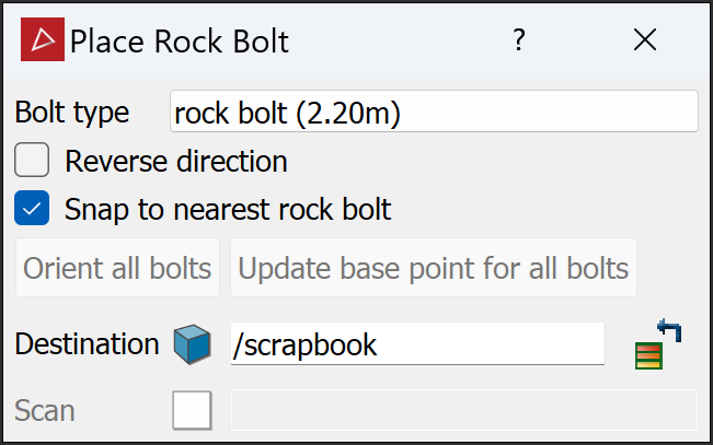
- Name, select, or drag in the Destination container. The default container is
scrapbook. -
Select the scan where you want to place rock bolts.
PointStudio will automatically analyse the scan for possible bolt locations.
-
Choose a Bolt type to place, or select Manage... from the bottom of the list to create custom rock bolts (see Creating a custom bolt).
Tip: Zoom in to analyse the surface easily.
-
Move the mouse around the scan and locate the missing rock bolts.
- Initially the new rock bolt will be coloured orange and will follow the mouse around the scan.
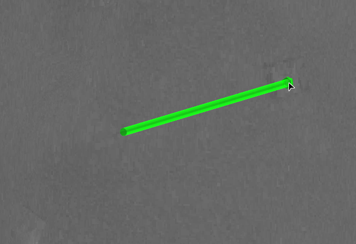
- The new rock bolt will turn yellow when near a possible valid location, and green when snapping to a location.
- If the rock bolt looks like it will be placed in the wrong direction, select Reverse direction. This may result from having multiple scan origins such that the inside of the tunnel cannot be distinguished from the outside of the tunnel.
- Clear Snap to nearest rock bolt if the snapped location (green) is not satisfactory.
- Click to anchor the bolt. Its colour will change according to the Bolt type.
Tip: With Reverse direction selected, you can click on Orient all bolts to reverse the direction of all manually placed bolts.
Note: You don't have to wait for the bolt to change colour to place it. If you are confident the bolt is in the right position even when red, click to anchor it.
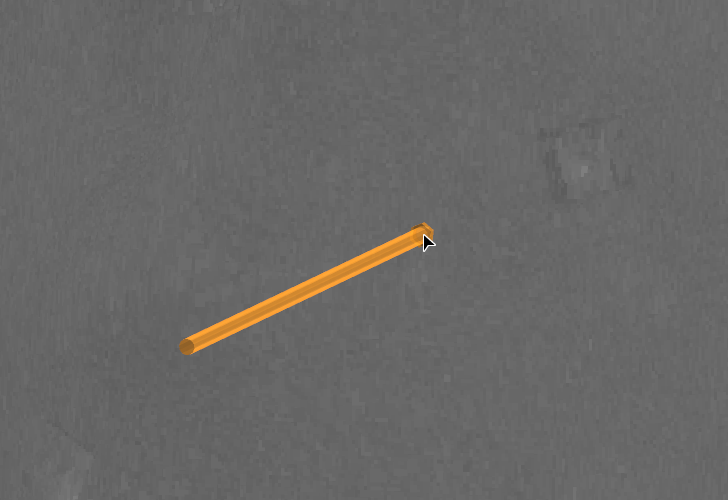
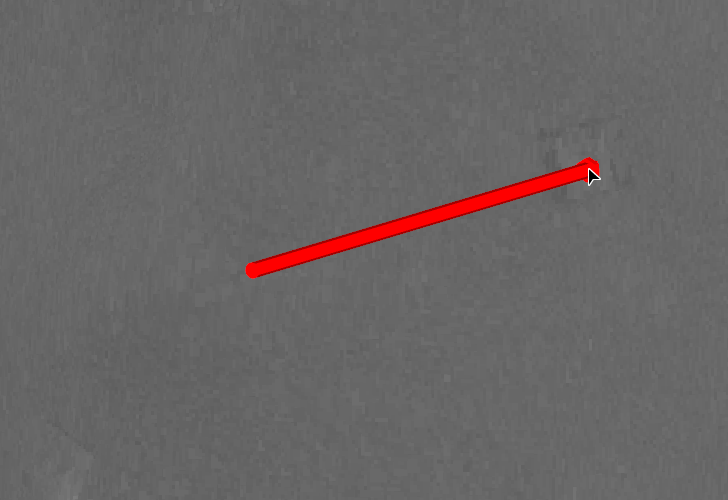
Orange bolt follows the mouse while looking for missed bolts.
Orange bolt snaps to a potential rock bolt location and turns green.
Click to acknowledge the position as a rock bolt; rock bolt turns the specified colour.
- Repeat steps 4 and 5 until all missing bolts have been placed.
- Click Update base point for all bolts to ensure that they are inserted in the tunnel surfaces to the right depths.
Tip: If you move the cursor back over the rock bolt, its colour will change to red. You can then click on it again to remove it.
|
|
|
In the above example the different colours represent a rock bolt in place (blue), a split set bolt in place (brown), and a cable bolt in place (purple). |
Removing incorrectly placed rock bolts
To remove an incorrectly placed rock bolt ![]() :
:
-
Move the mouse pointer near the bolt so that the bolt turns red.
-
Click and move the cursor away.
The rock bolt will be removed.
Rock Bolt Detection
Source file: rock-bolts-group.htm
The Rock Bolt Detection tool locates rock bolts on scans automatically.
Locating rock bolts automatically with Rock Bolt Detection
To locate rock bolts ![]() automatically:
automatically:
-
On the Query tab, in the Rock Bolts group, click
 Rock Bolt Detection.
The Rock Bolt Detection panel appears.
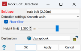
-
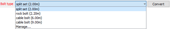
From the Bolt type drop-down list, select a bolt type to search for, or select Manage... to create a custom bolt (see Creating a custom bolt below).
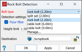
-
Select Floor Filter and enter a Height limit to set the minimum scanning height (meters). Only points above this limit will be scanned.
-
Name, select, or drag in the Destination container. The default container is
scrapbook. -
Click OK or Apply. The rock bolt detection tool will find all the rock bolts and place them in a sub-container labelled
rock bolts.
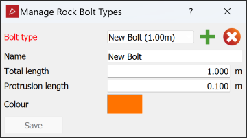
Creating a custom bolt
If a bolt type is not available in the drop-down list, you can create it using the rock bolt type manager tool. To create a custom bolt, select Manage... from the Bolt type drop-down list of the rock bolt detection tool.
Enter the new bolt type's details as appropriate and click Save.
|
|
|
In the above example we created a custom bolt type named |
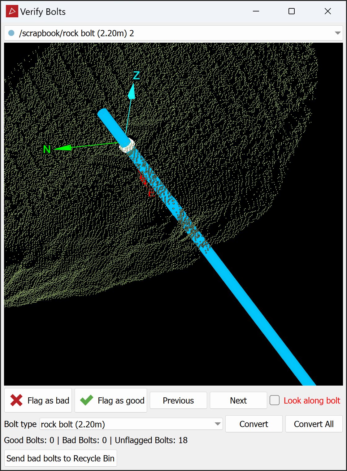
Verify Bolts
The Verify Bolts tool allows you to check automated rock bolt detection results and remove any false positives. False positives may result from other objects inside the tunnel that resemble rock bolts.
To verify automatically-detected rock bolts ![]() , follow these steps:
, follow these steps:
-
On the Query tab, in the Rock Bolts group, click
 Verify Bolts. The Verify Bolts panel appears.
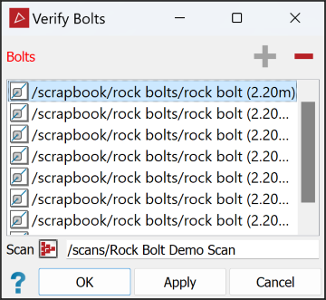
-
Review and flag each rock bolt:
-
In the Bolts list, select the rock bolts you want to analyse.
 Expand for detailed instructions
This field requires a rock bolt selection.
- To add items to the list, select individual rock bolts or containers of rock bolts in the project explorer, and click
 . Alternatively, drag and drop a selection of rock bolts from the project explorer into the list.
 - Click
 to remove items from the list.
- To add items to the list, select individual rock bolts or containers of rock bolts in the project explorer, and click
- In the Scan field, specify the source scan to verify the rock bolts against.
-
Click OK or Apply.
The Verify Bolts window will open and display a small section of the scan surrounding the rock bolt to analyse more closely.
Inspect the bolts one at a time.
Select Look along bolt to align the viewing angle with the bolt's axis. You can still maximise the window to full screen, zoom in or out, and rotate the image to achieve the best viewing angle for your decision.
Click Bolt type and select the correct type from the drop-down list. If it is not listed, click Manage... to create a custom bolt (see Creating a custom bolt below).
For a positive detection, click
 or for a false positive detection, click
  . The next bolt in the list will then be displayed.
Click Next or press Ctrl+↓ to move to the next bolt, leaving the current one unflagged.
Click Previous or press Ctrl+↑ move to the previous bolt, leaving the current one unflagged.
Press Ctrl+→ to flag the current bolt and move to the next bolt.
Press Ctrl+← to flag the current bolt and move to the previous bolt.
Click Send bad bolts to Recycle Bin to remove the bolts flagged as bad from the list.
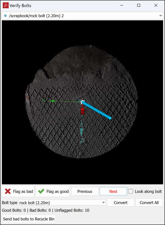
Step through the list, either flagging bolts or leaving them unflagged, as follows:
|
|
|
A positively detected rock bolt (left) compared to a false positive detection (right). |

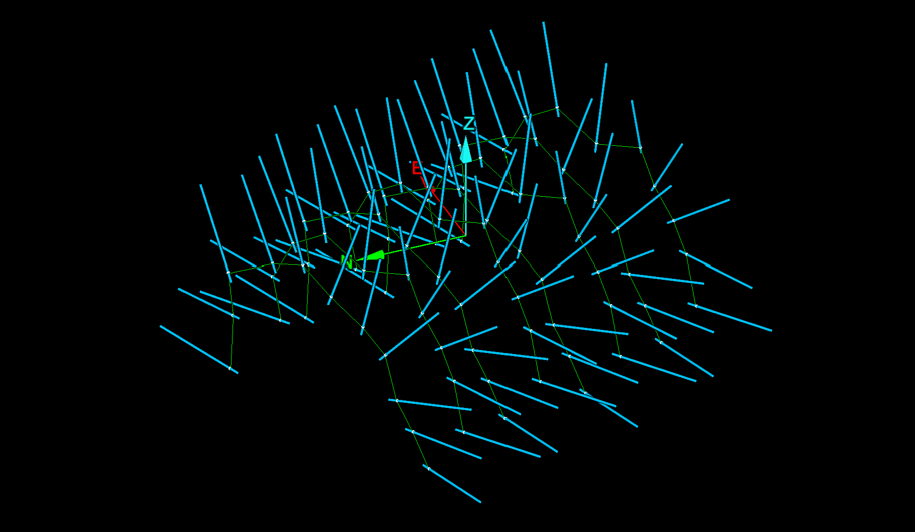
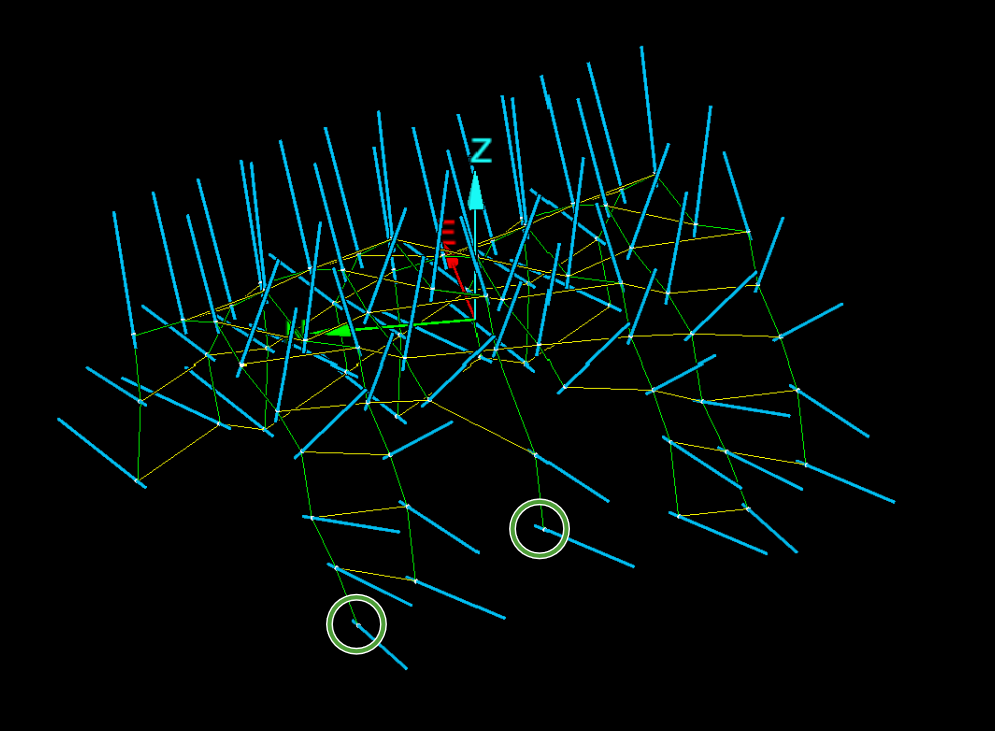
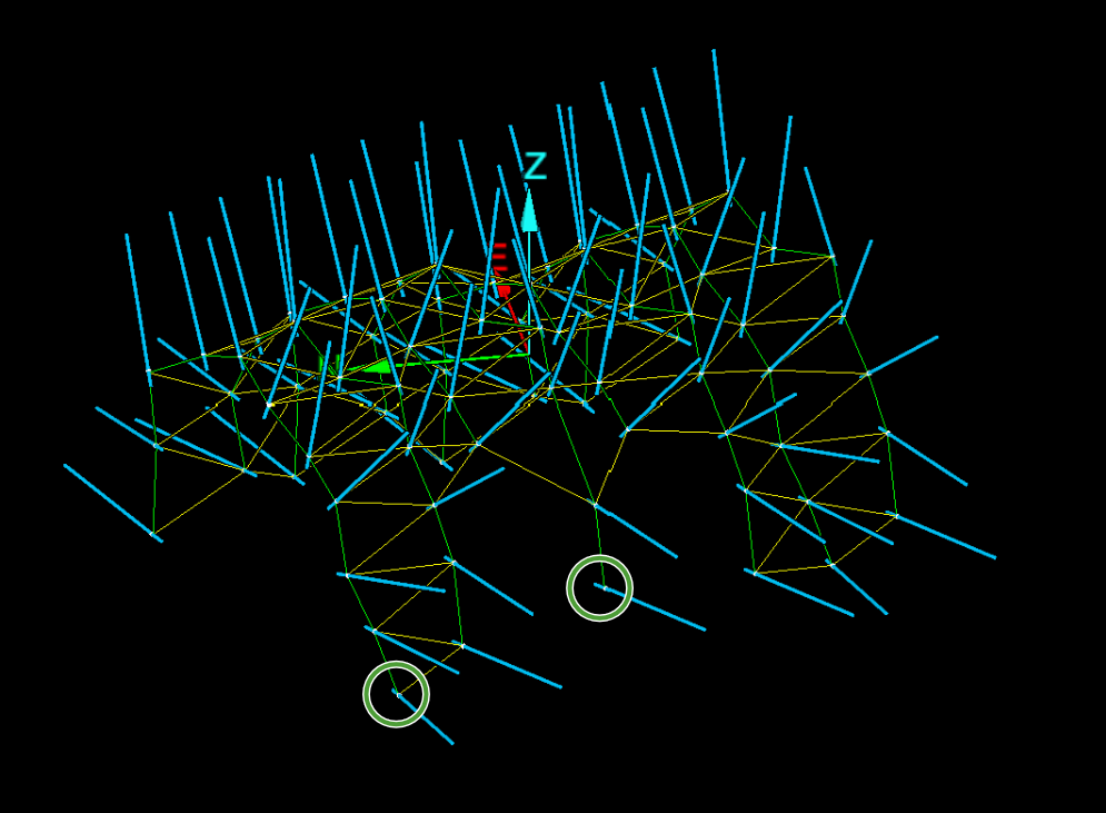
Create Bolt Network
The Create Bolt Network tools enable you to make connections between bolts in tunnel and wall modelling to assist with analysis, planning and reporting.
The bolt network tool can sort bolts into groups separated by division lines. For example, you can create separate groups for walls and ceilings. If you divide bolts into groups, the report tool will create a separate result for each group.
Bolts may occur in either orderly loops or in random placements. The bolt network tool allows for both arrangements. Expand below for instructions on each.
When bolts are arranged in orderly loops, create a loop network as follows.
-
On the Query tab, in the Rock Bolts group, select
 Create Bolt Loop Network from the Create Bolt Network drop-down. The Create Bolt Loop Network panel will open.
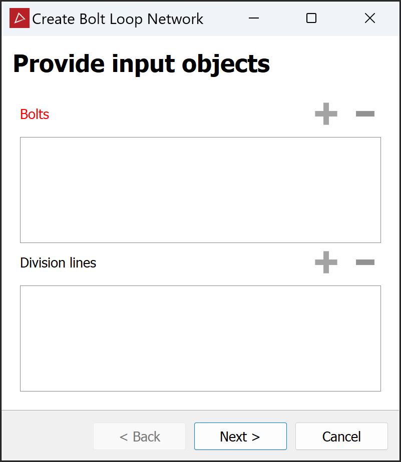
-
Add the rock bolts and optional division lines to the panel. To do this:
-
Drag them from the project explorer into the respective panel fields.
Or
-
Select them, then click the
 button for each panel field.
-
-
Click Next > to advance to the next page.
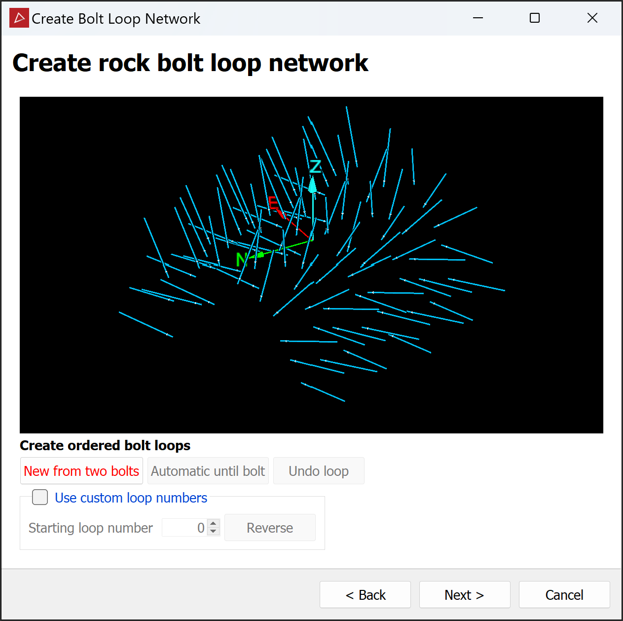
Note: Each page from here includes a previewer that you can manipulate in the same way as a view window, but without holding the Alt key.
-
Create ordered loops from the selected bolts. Click New from two bolts then:
-
In the tool panel preview, pick two bolts from a single loop. The tool will detect the loop and draw it as a yellow line through all that loop’s bolts.
Tip: For best results, pick bolts on opposite ends of the first loop.
-
Repeat step 4a to create more loops, or skip to step 4c.
Note: Only the current loop is yellow, indicating that it its editable. When you add a new loop, the previous loop changes to green.
-
Click Automatic until bolt and pick a bolt in the last loop. The tool will identify all loops automatically up to and including the last picked bolt and display them in the previewer.
-
-
(Optional) By default, loops are numbered starting from 0. You can change loop numbering to suit requirements, such as when adding to an existing bolt network. Select Use custom loop numbers and enter a new initial number in Starting loop number.
-
Click Reverse to order the loops in the opposite direction.
Note: The Use custom loop numbers option is available at all subsequent stages of loop network creation.
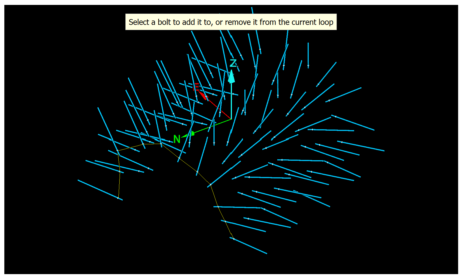
-
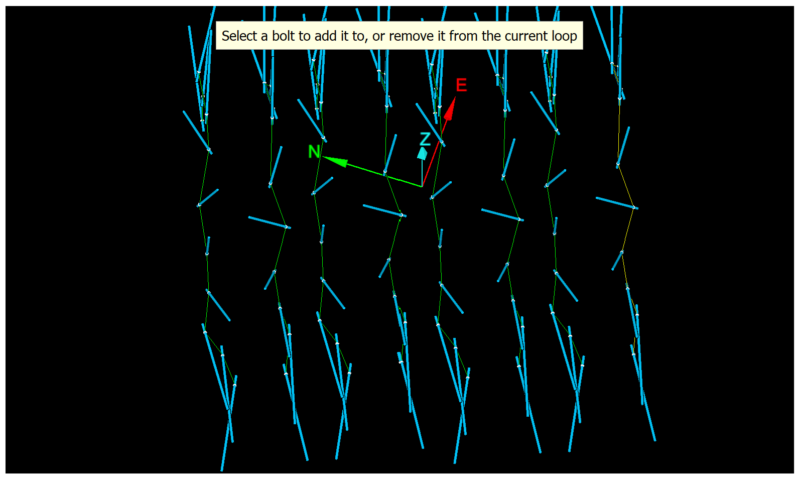
-
Inspect the loops to ensure that all bolts are correctly assigned. Occasionally bolts may be assigned to the wrong loops. If this occurs, correct them as follows:
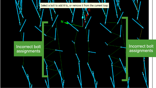
-
Take note of the incorrectly assigned bolts.
-
Click Undo loop until you reach the the first incorrectly placed bolt.
-
Pick the incorrectly placed bolt to add or remove it from the current loop.
-
Repeat step 4 to recreate the remaining loops, as above.
Tip: If there were numerous incorrect bolt assignments, click Automatically until bolt and pick the next problem bolt. Fix that bolt then repeat.
-
-
When the loops are satisfactory, click Next >.
The tool will add connections between loops, which will appear in the previewer as yellow lines, indicating that they are editable. Loops will be displayed green.
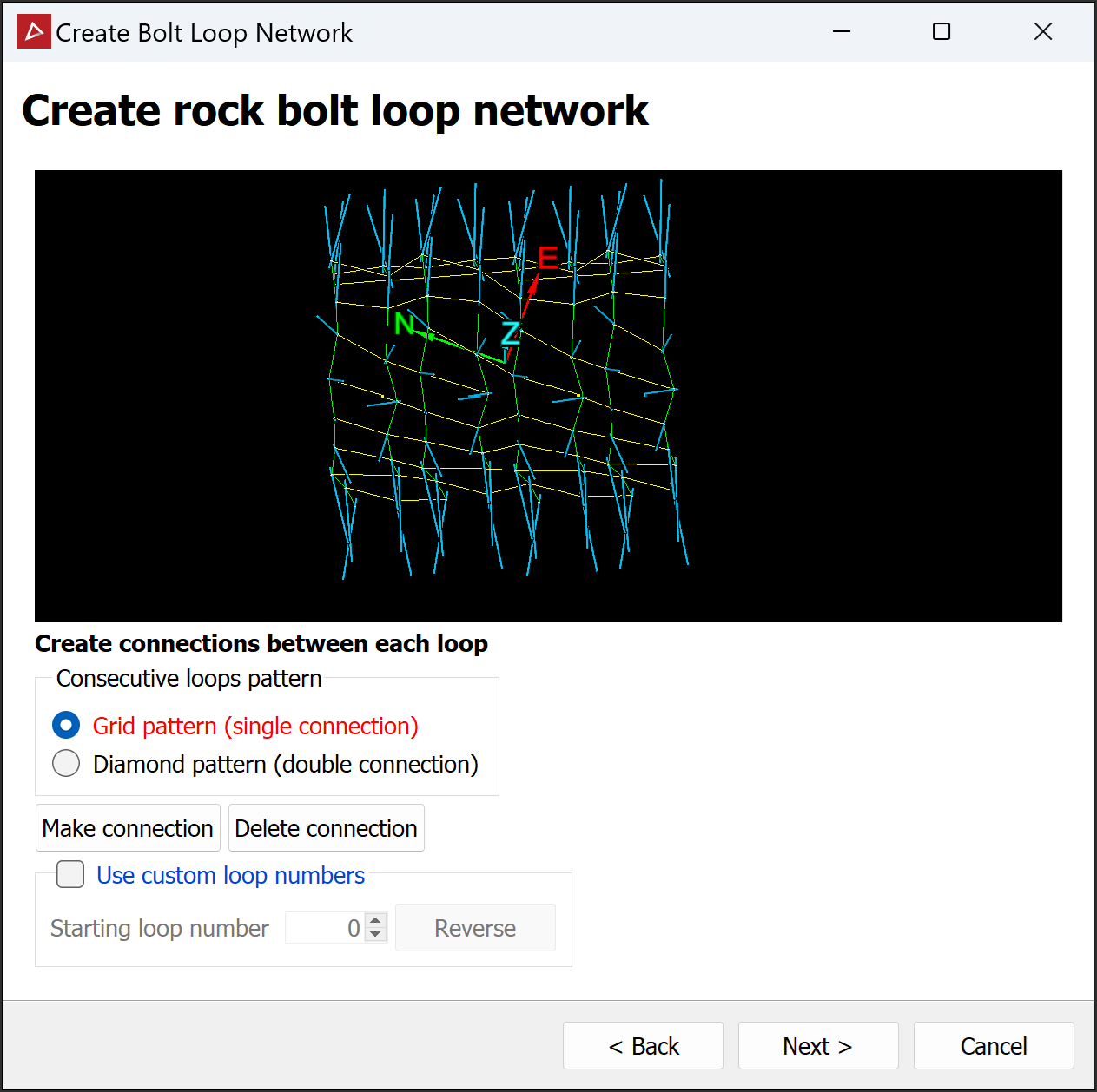
-
Select the preferred consecutive loops pattern:
-
Grid pattern creates single connections forwards and backwards between closest bolts in adjacent loops. Best when bolts are arranged in a rectangular grid.
-
Diamond pattern creates two connections forwards and backwards between bolts in adjacent loops. Best when bolt positions are staggered row to row.
Consecutive loops patterns on the same bolt set. The grid pattern (left) has bolts without forward or backward connections. The diamond pattern (right) attempts to make up to two forward and backward connections for each bolt.
-
-
Inspect the connections to ensure they are all correctly made. Fix any erroneous connections, as follows:
-
Click Make connection, then pick two bolts in adjacent loops to connect them.
Note: If the new connection conflicts with an older one, the older connection will be deleted.
-
Click Delete connection, then pick a connection between loops (yellow line) to remove it.
-
-
Click Next > to advance or, if you did not provide division lines, click Finish to close the tool and save the network.
If you provided division lines, the bolts will be coloured in the preview according to their groups. The loop network is unchanged.
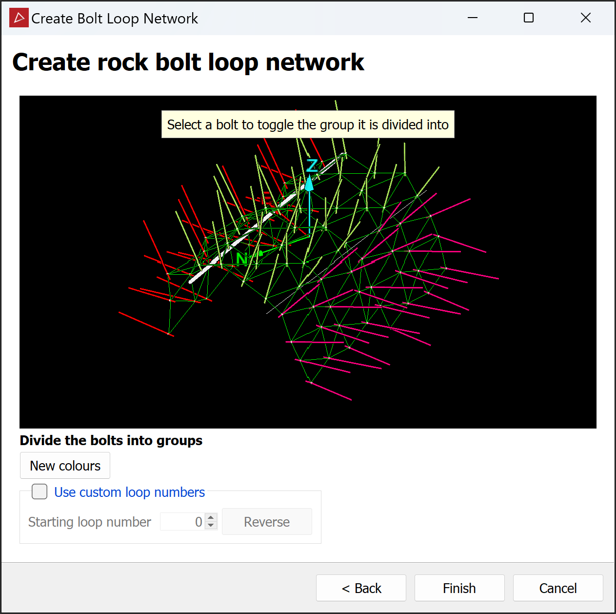
-
Inspect the groups and, if a bolt is incorrectly grouped, click on it until it appears in the correct group.
-
(Optional) Click New colours to switch to a different colour scheme. Repeat until you find a suitable scheme.
-
Click Finish.
The loop network is created and stored in the cad ![]() container.
container.
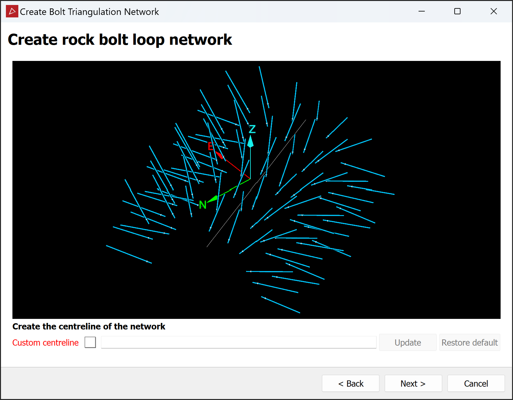
When bolts are placed randomly, create a triangulation network as follows.
-
On the Query tab, in the Rock Bolts group, select
 Create Bolt Triangulation Network from the Create Bolt Network drop-down. The Create Bolt Triangulation Network panel will open.
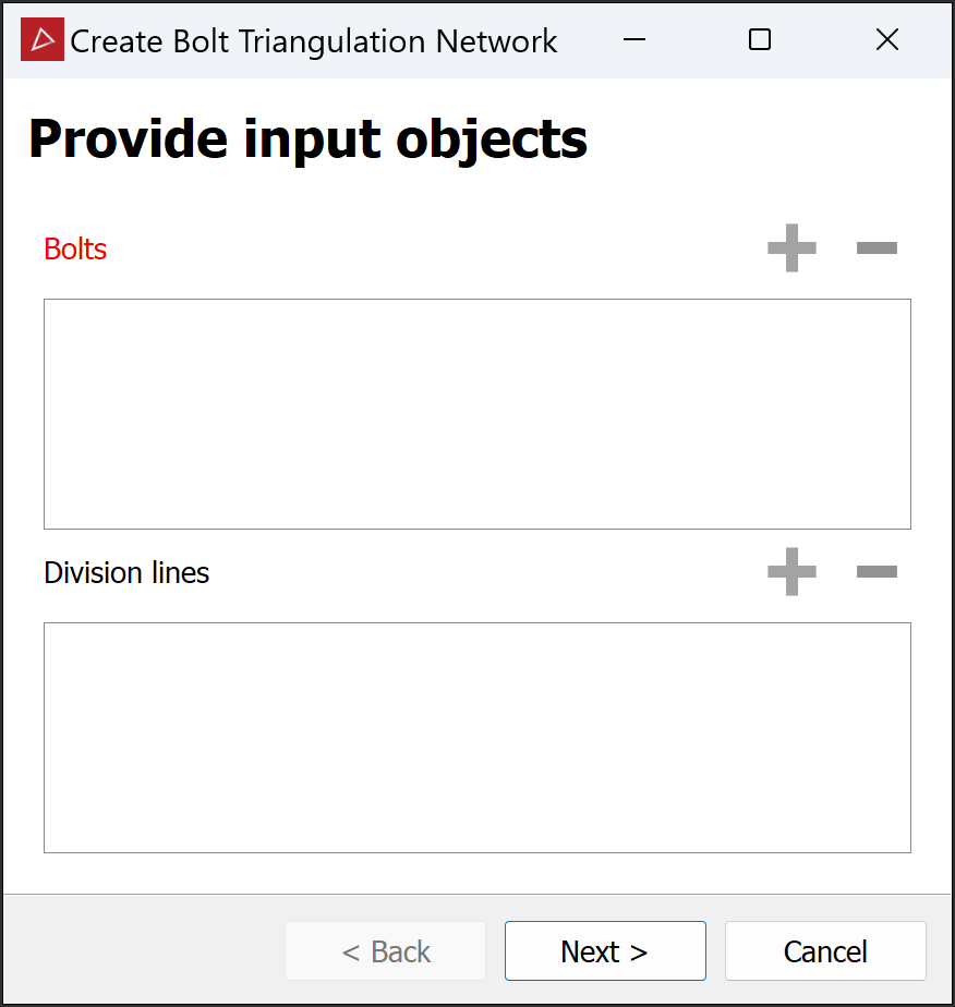
-
Add the rock bolts and optional division lines to the panel. To do this:
-
Drag them from the project explorer into the respective panel fields.
Or
-
Select them, then click the
button for each panel field.
-
-
Click Next > to advance to the next page.
Note: Each page from here includes a previewer that you can manipulate in the same way as a view window, but without holding the Alt key.
-
The triangulation network tool automatically generates a tunnel centreline. If the automatic centreline is incorrect, you can replace it as follows:
-
Drag a new centreline into the Custom centreline field from the project explorer.
Note: If necessary, draw a new centreline in a view window. See Lines.
-
Click Update to apply the new centreline.
-
If the custom centreline is not suitable, click Restore default to revert to the automatic centreline.
-
-
Click Next > to advance to the next page. The triangulation network tool will create and display a network.
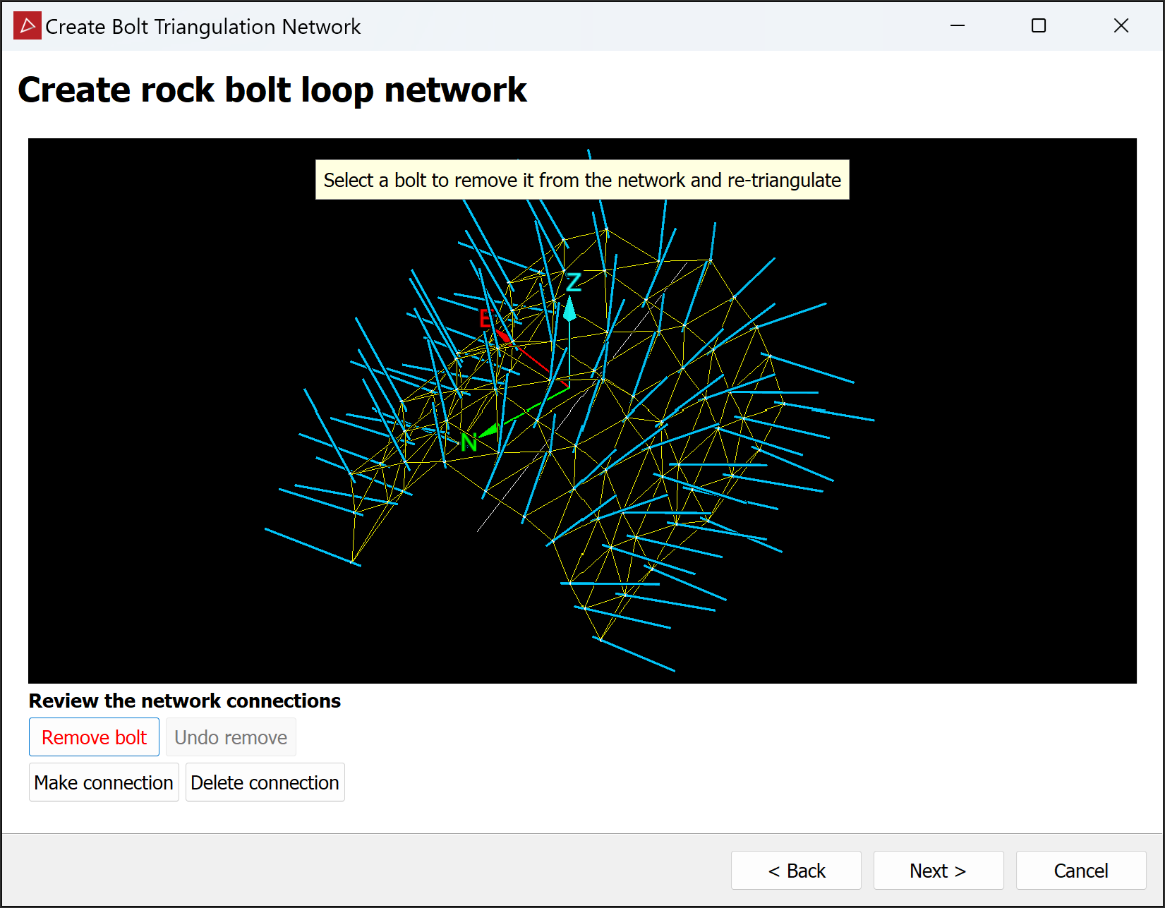
-
Inspect the connections to ensure they are all correctly made. Fix any erroneous connections, as follows:
-
Click Remove bolt, then pick a bolt to remove it from the network.
NoteRemoving a bolt will re-run the triangulation algorithm, so any other user changes will be lost.
Removed bolts are not deleted from the project.
-
Click Make connection, then pick two bolts to connect them.
-
Click Delete connection, then pick a connection to remove it.
Note: You will not be able to make or delete connections that would result in non-triangular spaces or holes.
Note: To repeat an operation, you must first click a button again.
-
-
Click Next > to advance or, if you did not provide division lines, click Finish to close the tool and save the network.
If you provided division lines, the bolts will be coloured in the preview according to their groups. The triangulation network is unchanged.
-
Inspect the groups and, if a bolt is incorrectly grouped, click on it until it appears in the correct group.
-
(Optional) Click New colours to switch to a different colour scheme. Repeat until you find a suitable scheme.
-
Click Finish.
The triangulation network is created and stored in the cad ![]() container.
container.
Rock Bolt Report
The Rock Bolt Report tool allows you to generate a PDF report that visually and numerically summarises the distribution of rock bolts.
Preparing the report configuration
Follow these steps to prepare the report configuration:
-
On the Query tab, in the Rock Bolts group, click
 Rock Bolt Report to open the Rock Bolts Report panel.
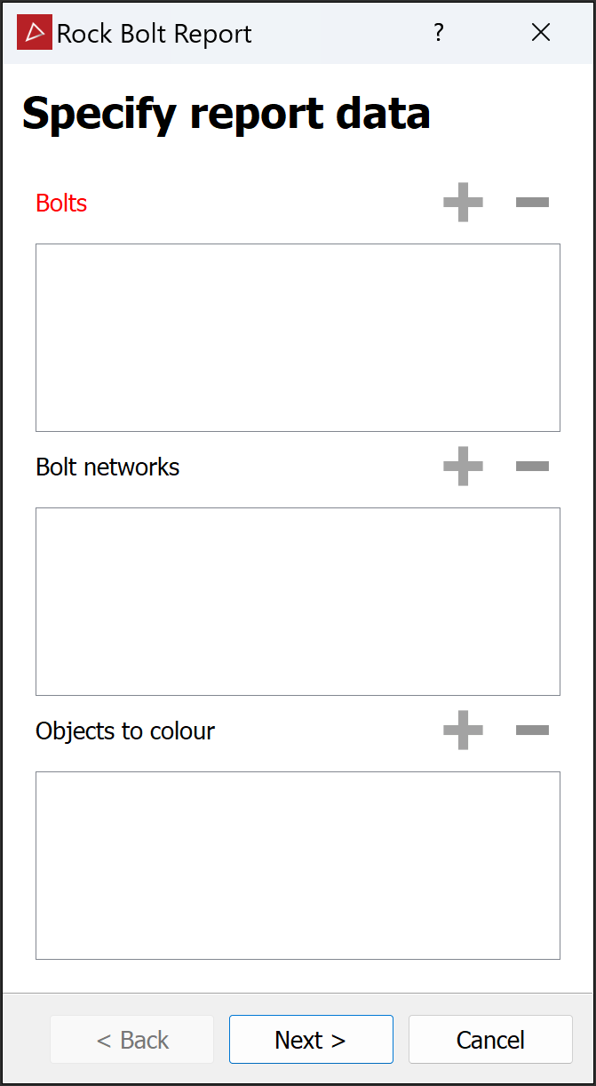
-
Select individual rock bolts
 or a whole rock bolts container. All detected bolts will appear in the Bolts field.
 -
Select individual bolt networks or a whole container with networks. All detected networks will appear in the Bolt networks field.
-
Select the scans or surfaces to be used to generate screenshots in the report. These will be scans the bolts were created from, or related surfaces.
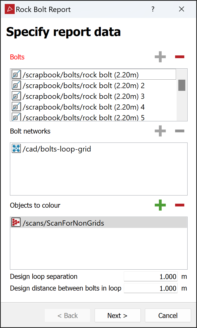
Note: The above fields have
and buttons for adding and removing objects. -
Depending on the network types selected, the following settings become available. Adjust the measurements to match design constraints:
-
Design loop separation – grid and diamond loop networks
-
Design distance between bolts in loops – grid and diamond loop networks
-
Design distance between bolts – triangulation networks
-
-
Click Next >.
-
-
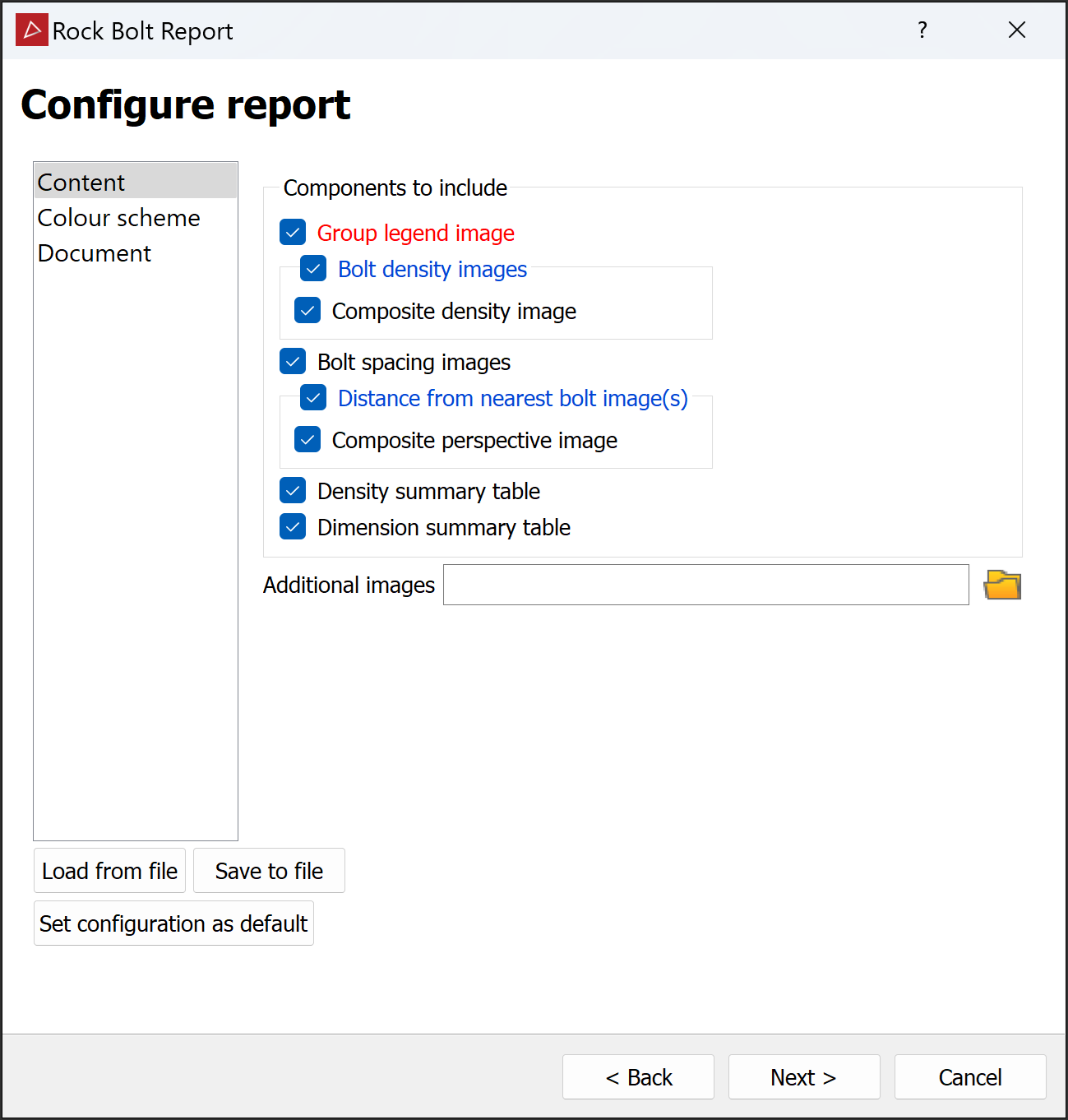
Configure report panel will open to adjust the look of the report and the data that will be displayed. Select the required options in the subsections as follows:
-
From the Content section, select components to include.
- Group legend image: Shows the different bolt group areas in distinct colours.
- Bolt density images: Shows the surfaces coloured according to bolt density. Select Composite density image to display all groups on one image.
- Bolt spacing images: Show the bolt network groups with connection lengths.
- Distance from nearest bolt image(s): Shows the scans coloured according to shortest distances between adjacent bolts. Select Composite perspective image to display all groups in one image.
- Density summary table: Include a table that summarises bolt density statistics by group and over all.
- Dimension summary table: Include a table that summarises bolt spacing statistics by group and over all.
- Any Additional images relevant to the job.
-
Set the Colour Scheme for the rock bolts and the cut-off distance between them.
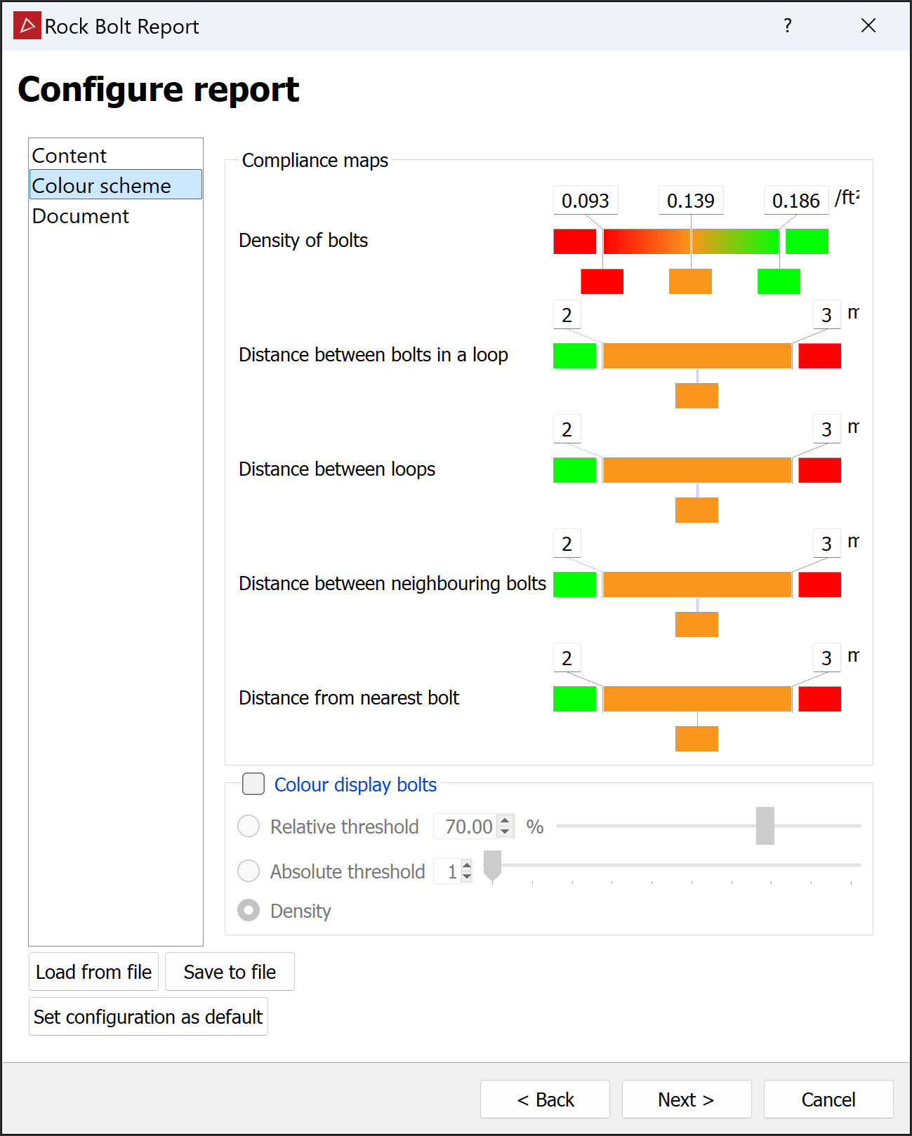
-
Adjust the Compliance maps as required. See Modifying a colour scale for detailed instructions.
- Select Colour display bolt to colour the bolt objects as well. Expand below for detailed instructions.
- Select Relative threshold to set the % of neighbouring bolts that fall beyond a colour boundary.
- Select Absolute threshold to give an explicit number of bolts instead of a percentage. For example, if a bolt is connected to 4 neighbouring bolts, one 0.5 m away, two 2.5 m away, and one 3.5 m away then, based on the compliance maps above:
- An absolute threshold of
2or3would cause that bolt to be coloured orange, because only one neighbour is ≥ the 3 m cut-off, but 3 of its neighbours are between the 2 m and 3 m cut-offs. -
An absolute threshold of
1would cause that bolt to be coloured red, because at least one of its neighbours is ≥ the 3 m cut-off. - An absolute threshold of
4would cause that bolt to be coloured green, because one of its neighbours is ≤ the 2 m cut-off.
- An absolute threshold of
-
Select Density to colour bolts by average proximity to neighbouring bolts.
Colour display bolt
-
-
In the Document section, add any required metadata and set a page layout.
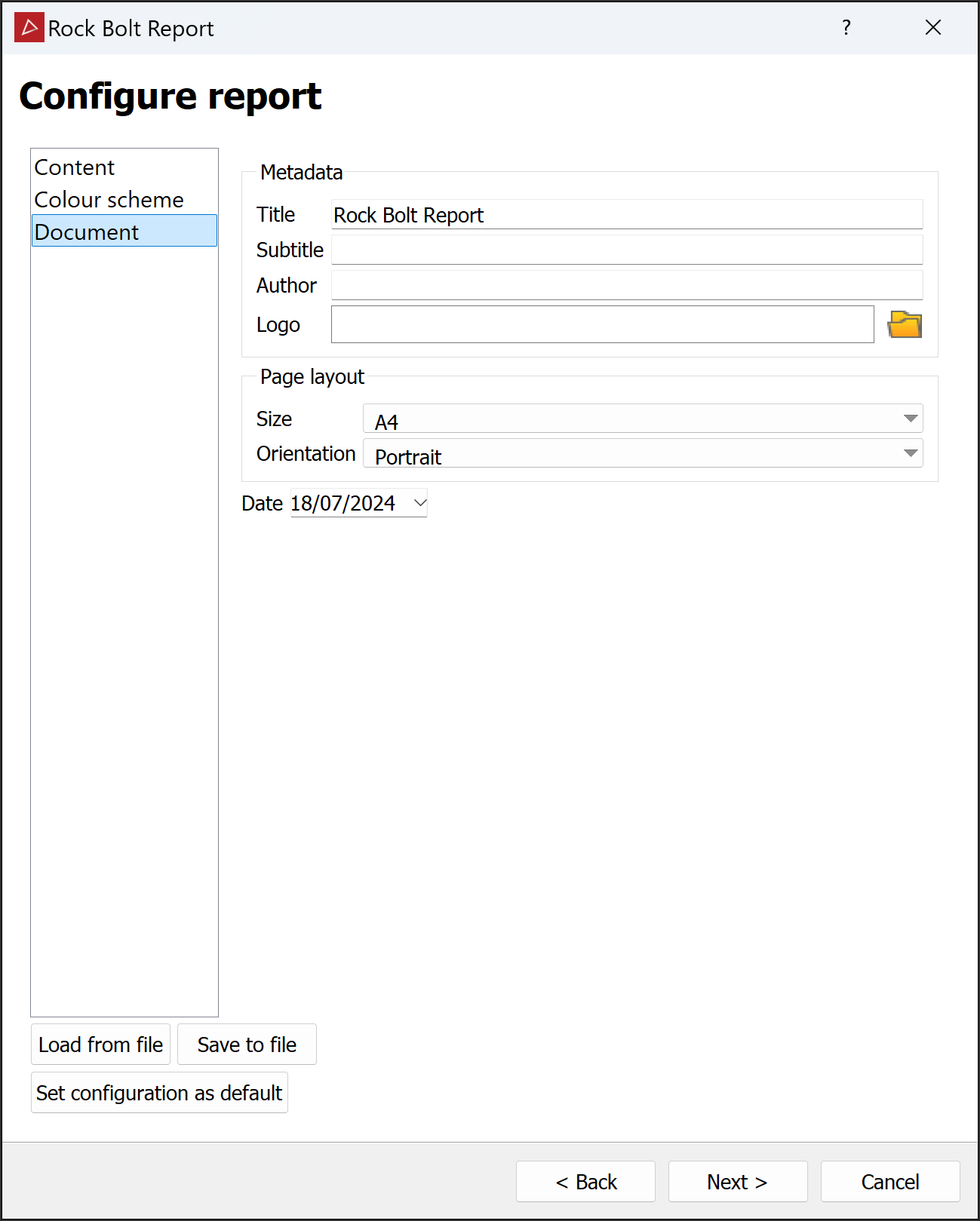
-
Note: You can save and recall report configurations to save time for future reports. Use the Load from file, Save to file and Set configuration as default buttons as required.
Finishing the report
Once the report configuration is complete, you can finish and publish the report.
-
Click Next > to generate the report content. The Review report images panel opens with options to edit the images. Editing is done using the Windows default image editor. Images can be reset following an edit.
You can also add images of data displayed in view windows. Click Add screenshot..., then enter the required image dimensions. When you click OK, PointStudio will insert a screenshot of the active view window area.
Tip: Before inserting a screenshot, ensure the view window is appropriately oriented and zoomed for the report.
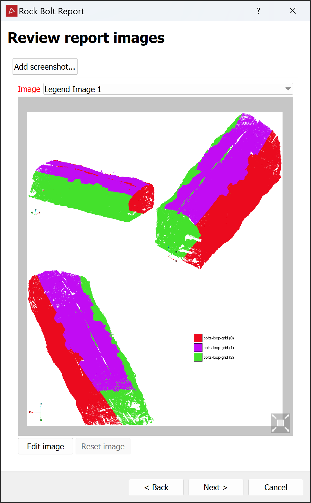
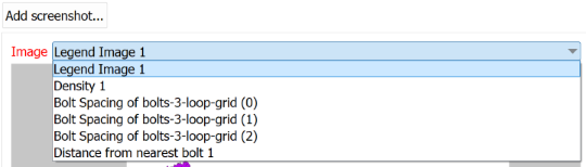
The Image drop-down list contains all the available images for review.
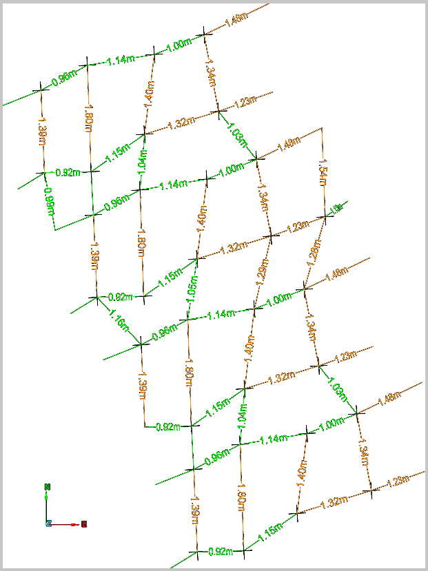
Example of the image of the Bolt Spacing of bolts-loop-grid (1)
- Click Next > on the Review report image panel to Preview report.
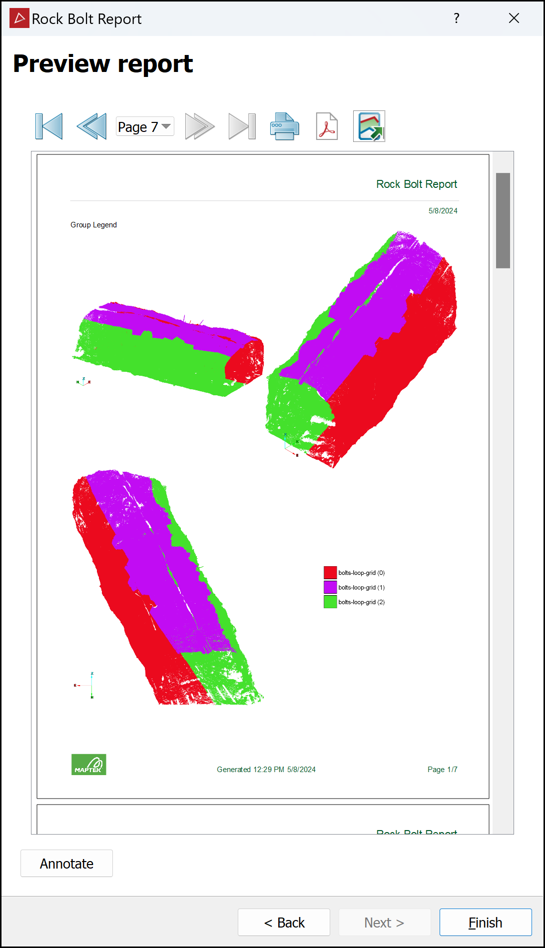
-
Click < Back to make any further changes.
-
Click Annotate to add comments to each section of the report before publishing.
-
Click
 to print the report.
-
Click
 to save the report as a PDF.
-
Click
 to save the report as a CSV or text file.
 -
Click Finish when done.
