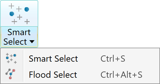
Selection
Source file: selection-group.htm
The Selection group provides tools for selecting specific data.

|
|
Smart Select (Ctrl+S) Expands primitive selection to include other primitives near the plane containing the current selection. |
|
|
Select By Select data by criteria from the drop-down list. |
|
|
All (Ctrl+A) Select all data visible in the view window. |
|
|
Invert (I) Select all visible data not currently selected; deselect all currently selected data. |
Smart Select
The Smart Select drop-down includes two tools for intelligently selecting points in contiguous sections of objects from an initial primitive selection.
Expand below for detail on using each tool.
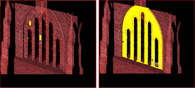
Smart Select (Ctrl+S) uses seeding point, edge, or facet selections to expand the selection, as follows:
- Point selections on surfaces or scans are expanded by picking other points close to the plane that the current point selection is on.
- Point and edge selections on edge networks are extended by flood-selecting all the points or edges connected to the current selection.
- Facet selections are extended by selecting other facets close to the plane that the current facet selection is on.
To run smart select:
-
Using the
 (Select points) type, select the seed primitives. Hold down Shift to select as many areas as needed.
 -
On the Home tab, in the Selection group, click
 Smart Select.
 -
Click the Smart Select tool until the desired selections are seen.
Note: If you previously used Flood Select, you can find Smart Select in the tool’s drop-down.
|
|
|
|
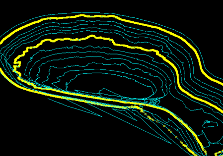
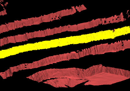
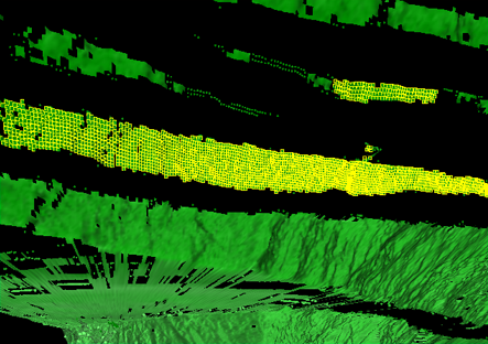
The Flood Select tool expands the selection of primitives to all connected primitives.
Note: Flood selection can only be used on points that have been connected first. See Scan > Connect or Smart Connect.
You can also run flood select on edge networks to extract a selection of contours, which can subsequently be exploded. See Fix > Explode.
Tip: Try using Smart Select if Flood Select does not select the required data. See Smart Select, above.
After making an initial selection, go to the Home tab, Selection group. From the Smart Select drop-down list, select ![]() Flood Select.
Flood Select.
|
|
|
|
Flood selection on edges. |
|

|
|
|
|
Flood selection on facets. |
|

|
|
|
|
Flood selection on cells. |
|

Select By
The Select By drop-down provides three methods for selecting data.
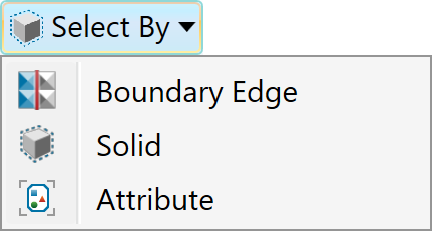
Expand below for details of each selection method.
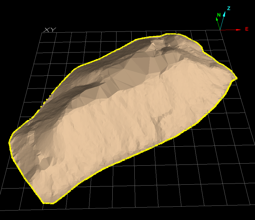
Select by Boundary Edge selects all
connecting line segments comprising the outside boundary of a surface ![]()
![]() .
.
To select by boundary edge, follow these steps:
-
On the Home tab, go to the Selection group. From the Select By drop-down list, select
 Boundary Edge.
 -
Pick a section of the boundary or edge of the surface of interest.
All line segments comprising the boundary will be selected.
|
|
|
All line segments of a boundary selected after clicking on a section of the boundary of the surface. |
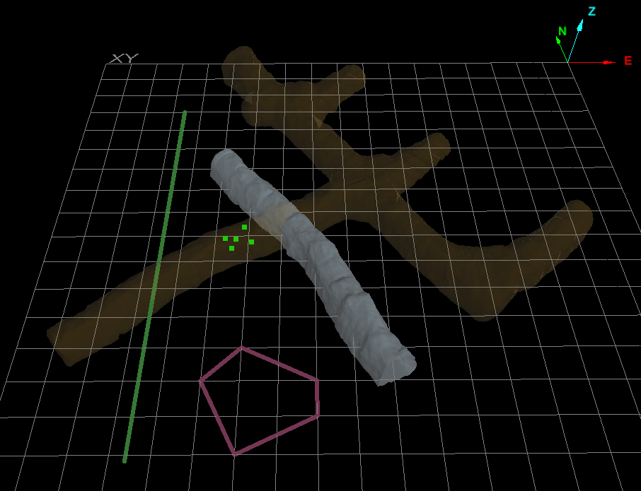
Select by solid allows you to select all objects associated in some way with a particular solid surface object. Selection policies give you options for comparing spatial relationships. For example, you can select all objects inside, outside or intersecting a particular solid shape, or all those that are either outside or intersecting the particular solid.
Note: For the Select by Solid tool to work, the object used as the selection policy’s reference must be a closed solid. That is, it must not have holes.
To select by solid, do the following:
-
Select all objects to be filtered by the selection policy.
-
On the Home tab, go to the Selection group. From the Select By drop-down list, select
 Solid.
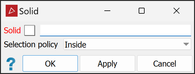
-
Click on the particular solid surface to reference in the view window; the Solid field of the tool panel will auto-populate . Alternatively, drag the solid surface from the project explorer into the Solid field.
-
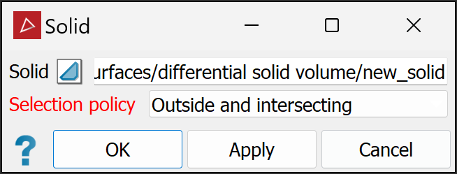
Select the required option from the Selection policy drop-down menu. The following options are available:
- Inside
- Inside and intersecting
- Intersecting
- Outside and intersecting
- Outside
-
Click OK or Apply to process.
-
The objects meeting the selection policy will remain selected. Others will be de-selected.
-
Where two criteria are used in the selection policy, an object only has to satisfy one criterion to be selected.
|
|
|
Objects intersecting, inside and outside the main complex solid surface (translucent orange), to be used as the reference solid. |
|
|
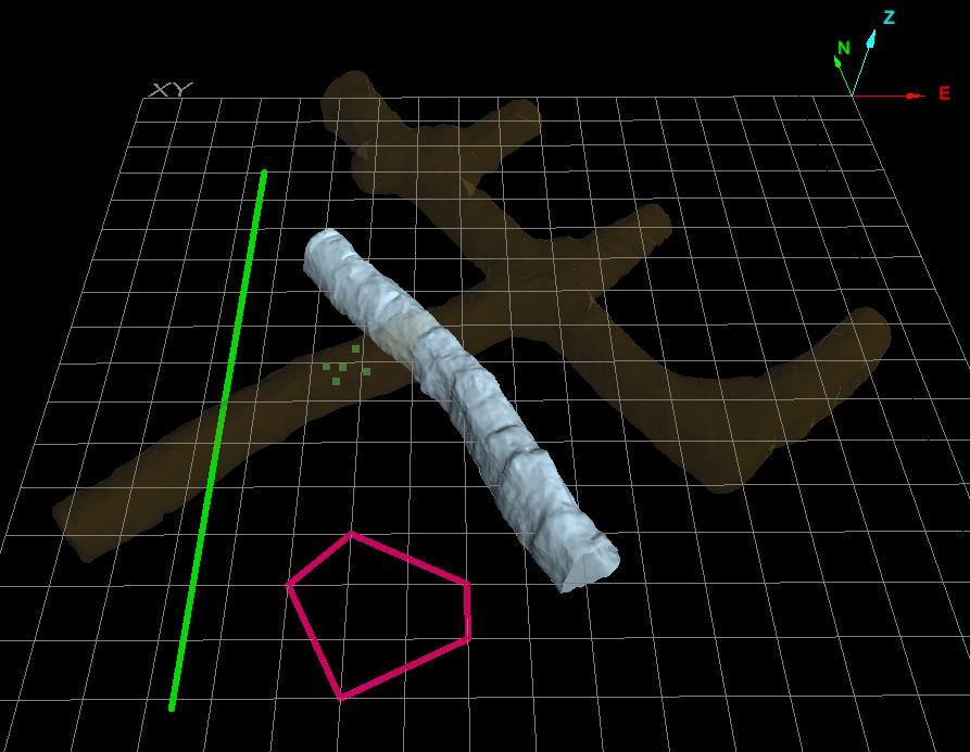
Selection policy set to look for objects either outside the reference solid or intersecting it. |
|
|
|
The selected objects met the criteria of the selection policy: the line and the tunnel intersect the main complex solid and the pink polygon lies outside the complex surface. The points are inside the complex solid, so they are not selected. |
Select by Attribute allows you to select objects based on their available attributes.
Tip: For assistance with creating attributes, see Attributes > Create Attributes.
To select by attributes, follow these steps:
-
On the Home tab, go to the Selection group. From the Select By drop-down list click
 Attribute.
The Select by Attribute panel will appear.
-
Select the object from the project explorer.
-
Choose an Attribute type from the following:
- Object Tags: Objects can be given tags that can then be used as attributes.
- Primitive type tags: You can give primitives tags that can then be used as attributes.
- Primitive type properties: Different object type primitives will have different properties that can be used as attributes. For example, with scans you can select from the following attributes:
- Intensity
- Range
- Z coordinate
If you have previously coloured an object by distance (see Distance from Objects), the Attribute list will also include Distance from objects.
Any user-defined attributes with integer-type tags will also be available on the Attribute list.
Note
Note: The primitive properties and tags options also allow you to combine the selection with previously applied filters. See Filter > Filter Combinations for a detailed explanation.
-
Select the required Attribute from the drop-down list.
-
Select one of the following Range criteria from the drop-down list, as required:
-
The typical intensity range using a Maptek Gen3 MkI or MkII scanner varies between 350 and 1400.
-
The typical range captured by a Maptek Gen3 MkI or MkII scanner is from 2.5 to 2400 m.
-
(Optional) If available, enter text to search for in the Matches field. For example, to filter objects with an attribute called Water, type
Water.-
Select Use wild-card matching to filter key words in attributes, with
*as the wild-card. For example, to filter all attributes containing Water, type*Water*in the Matches field. -
Select Case-sensitive to include only results that match the case of the search item. With the previous example, a case-sensitive search will exclude results containing
water.
-
-
(Optional) Select the Invert checkbox to exclude objects identified by the Range and Matches criteria. With the previous example, results will exclude objects with the attribute
Water. -
Click OK or Apply.
|
|
Range Enter values in the From and To fields. |
|
|
Less than or equal Enter the upper range limit required. |
|
|
Greater than or equal Enter the lower range limit required. |
|
|
Equal Enter the exact attribute value required. |
|
|
All finite values Filter out attributes that have invalid values. |
The selection will be made based on the criteria you have specified.
