Angle/Distance
Measure the Angle and Distance Between Two Lines in Space
Use the Angle/Distance option to measure the angle and shortest (perpendicular) distance between two nominated lines. The measurements displays in the Report Window. The window displays the 3D angle, the perpendicular distance, and the angle projected onto the XY plane.
This option can also be accessed by selecting the Angle Distance button from the Analyse toolbar.
Instructions
Click Angle Distance ![]() on the Analyse toolbar.
on the Analyse toolbar.
or
On the Analyse menu, point to Details, and then click Angle/Distance to display the Analyse Angle/Distance panel.
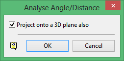
Project onto a 3D plane also
Select this check box to project the lines onto a 3D plane.
Click OK.
If you selected the Project using a 3D plane also check box, the Projection onto a Plane panel displays.
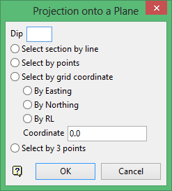
Dip
The dip is the angle of the section from horizontal. Valid dip angles are between -90° and 90°.
Select section by line
Select this option to define the plane by selecting an existing line and specifying the dip. Only design strings may be picked and it is not possible to pick a line in an underlay. The direction of the view, and therefore the direction of the stepping, depends on the digitised sequence of the line. The digitised sequence of the line can be reversed using the Reverse option (under the Design > Object Edit submenu).
Select by points
Select this option to define the plane by digitising two points and specifying the dip. To locate a point precisely, use the Snap to Objects ![]() or Snap to Points
or Snap to Points ![]() mode on the Digitise toolbar. Points may be snapped onto underlays, such as block model slices or triangulations. If you use Indicate
mode on the Digitise toolbar. Points may be snapped onto underlays, such as block model slices or triangulations. If you use Indicate ![]() mode to select points, they will have the current default Z value.
mode to select points, they will have the current default Z value.
![]()
Select by grid coordinate
Select this option to define the plane by using a specific grid coordinate. The grid coordinate can contain up to three decimal places. To achieve the best results for the following three method, we recommend using the Zoom Data Extents ![]() mode on the Graphics toolbar to view all of the graphics.
mode on the Graphics toolbar to view all of the graphics.
![]()
Select by 3 points
Select this option to define the plane by digitising 3 points. To locate a point precisely, use the Snap to Objects ![]() or Snap to Points
or Snap to Points ![]() mode on the Digitise toolbar.
mode on the Digitise toolbar.
![]()
Points may be snapped onto underlays, such as block model slices or triangulations. When you use this option, you can explicitly define the location and orientation of a lane by indicating 3 points. The first two points define the bearing of the plane, and the third point defines the dip of the plane.
Select the object that contains one of the lines, followed by the line segment. You will need to confirm that you have selected the correct line segment.
Select the object that contains the other line segment, followed by the second line segment. Again, you will need to confirm that you have selected the correct line segment.
The results displays through the Report Window. Select two more lines or right-click to exit the option.
If the current view is a rotated view, then the Report window will show the angle made by the lines in the current view.
If the Project onto a 3D Plane option was selected, the Report window will also show the angle between the lines projected onto this plane, along with the angle of these lines projected to the XY plane. If the projected lines are parallel, the separation distance is also shown.

