Reserve Calculation Techniques
Using Benching and Batters - Step 1
Rsvute can also be used to calculate and report reserves on a bench by bench basis. This allows the mining engineer to create a design that incorporates pit-wall benching and batters. A block layout is created for each mining horizon and saved in a layer. Reserves are then reported as a spreadsheet dump table. Combining the tables for each bench, the engineer can produce a workbook of reserves representing true, "layback", bench by bench reserves. This technique is illustrated below using a pit design (DEMO) created in Vulcan with the Open Pit > Benching and Batters submenu.

Diagram 1 - Pit Design
The limiting topography surface and the sequence of horizons is specified in your Benching and Batters specification file (.bb_spec). This file is generated through the Set Up option.
The steps required to use Rsvute for layback reserve calculations are:
-
Create a set of mining bench grids Based on the coal seam grids and topography, first create a set of mining bench grids, mid-bench grids and bench thickness grids (Diagram 2). A
Grid Calc macro
can be written to create these grids.
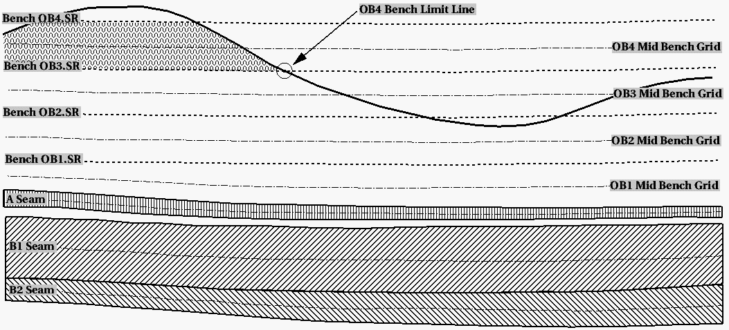
Diagram 2 - Stratigraphic Cross Section through Geological Model and Overburden Grids
-
Generate seam and burden bench limits
Using another Grid Calc macro, create limit polygons for each bench. Store them in a design database for use in Rsvute. Each bench limit line is generated from the intersection of the bench toe grid and topography (Diagram 2).
Coal seams may have "no coal" and "sub-crop" polygons that make up coal bench limits. Diagram 3 shows the reserve area under consideration. The green polygon is the proposed mine area. The shaded area is the polygon created by a Grid Calc macro for the overburden bench 4. The naming convention used for limit polygon layers is<bench>LIM, for exampleOB4LIM.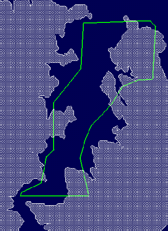
Diagram 3 - OB4 Limit Polygon -
Create bench and batter walls from the pit design polygon
Using Open Pit > Benching and Batters, create pit walls based on the pit design polygon shown in Diagram 3. End wall lines are created around the perimeter. Face wall lines are created based on strip widths and sidewalls are created based on the mining block widths.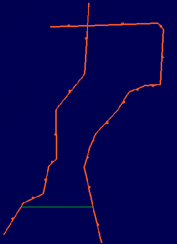
Diagram 4 - End wall Lines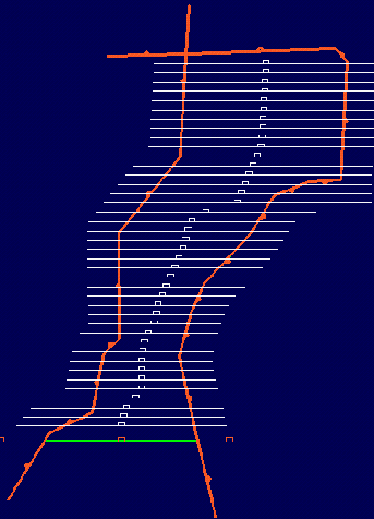
Diagram 5 - Face wall Lines
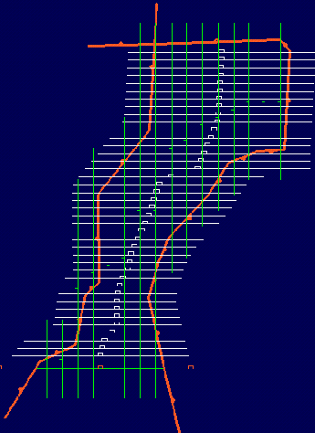
Diagram 6 - Sidewall Lines -
Project walls
Apply a benching and batters projection macro that projects the walls according to the desired layback design. Note that the walls are projected from theB2.SRgrid (toe) up to each Mid Bench grid, then to each bench crest. The projections that fall on the Mid Bench grids are used to create bench by bench block layouts for use in Rsvute.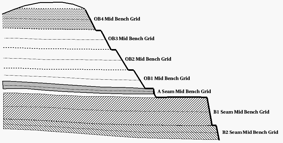
Diagram 7 - End wall Layback Design
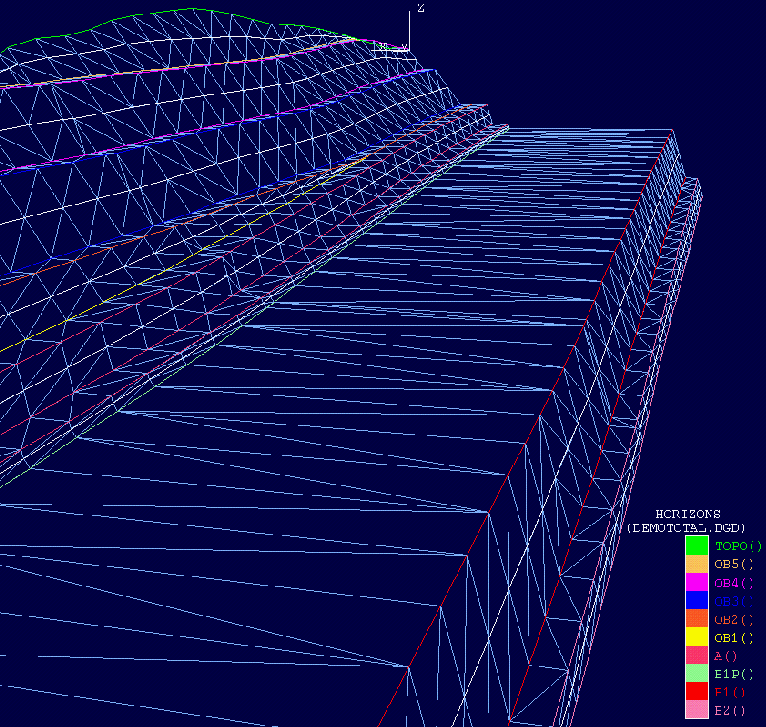
Diagram 8 - Wireframe Perspective of Benching and Batters End wall Projection
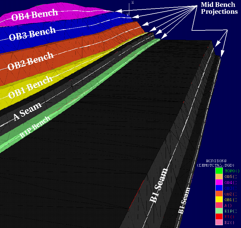
Diagram 9 - Solid Shaded Perspective of Benching and Batters End wall Projection
-
Create a block layout on each mining bench
Use the Horizon Visibility option (under the Open Pit > Benching and Batters submenu) to make individual mid bench wall projections. From these, use the Build option (under the Design > Polygon Edit submenu) to create a projected block layout according to the design. Save each of the mid bench block layouts in layers named after the mining bench, for example B2, B1, B1P, A, OB1, OB2, OB3, OB4, OB5.
Each of the bench block polygons must have a logical sequence name, for example S1B5 (Strip 1, Block 5). The task of naming each of the blocks is made easier by using the Naming option (under the Open Pit > Pit Layout submenu). This option to click on each polygon and have it named according to a strip or block sequence.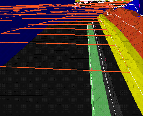
Diagram 10 - Block Layout on OB1 Mid Bench
-
Create Rsvute Reserving Macros
Create a series of Rsvute macros that load appropriate coal or burden specifications, load each mid bench block layer, dump reserves to a table and put them into spreadsheet table format. A Shell script can be written to run these macros.

