Edit Display Attributes
Use this option to modify the display attribute settings for the currently loaded Drill and Blast holes. Through this option you will be able to control attributes such as collar and downhole annotations, hole colours, etc.
Instructions
Click the  Edit Display Attributes button from the Drill and Blast - Edit toolbar.
Or
On the Drill and Blast menu, point to Edit, then click Edit Display Attributes.
The Select hole(s) dialog box is then displayed.
Using the displayed dialog box, nominate a method by which to select the holes. You have the choice of selecting By Hole, By Row, or By Echelon. Use the All Holes option to edit all of the holes from a particular blast.
Once holes are selected, the Display Attributes panel displays.
Click the Select All option to edit each of the available display attributes. Once selected, all of the check boxes displayed through the panel will be checked. Pressing the Deselect All option will clear all of the displayed check boxes, preventing you from editing any of the attributes.
To edit a single attribute, click the Deselect All option before checking the appropriate check box.
If you only want to alter the size of the displayed collar symbol for all of the selected holes, then you would need to click the Deselect All option before checking the check box that displays next to the Symbol size field.
Collar Annotations tab
Use the Collar Annotations section to define which hole collar annotations to display as well as the annotation properties, that is font type, the size of the annotation text, etc. The collar annotations will be created at the same elevation as the collar point.
Collar Annotations
Label
Select this check box if you want to display the associated collar value, i.e. hole name, hole depth etc, within an annotation label.
Colour
Select the colour that will be used when displaying the hole collar labels.
Label Prefix
Enter a prefix (a maximum of 5 alphanumeric characters). Label prefixes are appended to the start of the chosen hole collar label.
Position
Specify the position at which to display the annotation label, i.e. left, right or centre.
In order to prevent labels being placed on top of each other, we recommend that you position each label at a different position.
Annotation Properties
Font
Select the required font from the drop-down list.
Text drafting size
Enter the size, in plotter units, of the text. This will be the size of the text on the print out. If the font is a transformable font, i.e. a scaled font, then the size will be in relation to the map scale. Annotations lie in a straight line, i.e. the text does not curve.
The font used for the annotations is specified through the Defaults : 2D Text section of the Tools > Preferences option.
Map scale
Enter the map scale for the text annotations.
If the size is set to 0.30 and the map scale to 1:100, then the text will appear on the screen the same size as an object that is 30 units tall. Changing the scale, in either this option or the File > Plot > Plot All option, to 1:1000 results in the text appearing as 300 units. Changing the scale to 10 000 results in a text size of 3000 units and so forth.
Rotation of lettering
Enter the angle at which the annotation text will appear. Fixed fonts will always be displayed horizontally when viewed onscreen. The resulting text, however, will appear at the correct angle when plotted.
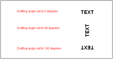
Figure 1: Rotation of lettering examples
Number of decimal places for numeric labels
Enter the maximum number of decimal places for the annotation labels.
Downhole Annotations tab
Click OK.
It is also possible to edit the display attributes through the Vulcan context menu, as well as through the Edit Holes option (via the Display Attributes column of the Edit Holes panel).
To edit the display attributes through the Vulcan context menu, right-click on the desired hole(s) and select Edit Attributes from the displayed context menu.
The context menu can also be used to hide/display primitives around selected holes. Select the Primitive On option if you want to display a circular primitive, which shows the area of affectation, around selected holes. The diameter of the applied primitive will be equal to the minimum of the burden and spacing values.

