Batch Plotting
Use the Batch Plotting option to set up and then run specification files that will be used when plotting either single or groups (batches) of plots that contain drill holes, digitised data (design files), triangulations, grid or block models and composite data. None of these data types need to be loaded on the screen in Vulcan to use this option. However, it is possible to fill quickly the specification file with what is on the screen. Plots may include multiple views (Section, Plan and Width).
The specification file in which the information is stored has the format:
<proj><spec_id>.dh2
Resulting plot files are named:
<proj><spec_id><n>.dhq
where n = a number and applies to multiple plot generation.
Note: The Cross Section option can be used as an alternative for producing section plots of triangulations and grid models.
Plot Files may be very large (750,000 objects or more). If the plot file becomes too large to plot or load into Plot Edit, the following can be used to lower the size of the plot file:
- Turn off one or more of the multiple views.
- Turn off one or more of the views for digitised drafting, grid models and triangulations.
- Turn off the polygon mode for drill holes. Use a larger line thickness instead.
- Turn on section view if using triangulations.
- Don't use wildcards for digitised drafting or triangulations.
- Try using a different, simpler font. More complex fonts, such as Times will add to the size of the plot.
Note: When creating a new specification file, if you load all of the data you want to include on the plot(s) on the screen and check the Default drill holes, design layers, grid models, triangulations and block model to those currently loaded in Vulcan check box, then you will not need to complete as many panels in the Data Elements section.
Instructions
On the File menu, point to Plot, and then click Batch Plotting to display the Batch Plotting Identifier panel.
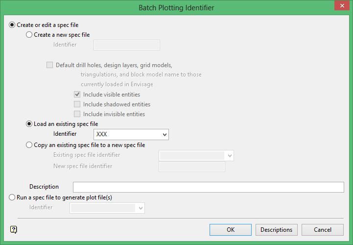
Create or edit a spec file
Select this option to create a new plot specification file (.dh2) or edit an existing one.
Create a new spec file
Select this option to create a new specification file. You will be required to enter an identifier. This identifier is the <spec_id> part of the specification file name. The maximum size of the identifier is 12 alphanumeric characters (do not use spaces in the name).
Select this option to create a new specification file. You will be required to enter an identifier. This identifier is the <spec_id> part of the specification file name. The maximum size of the identifier is 50 alphanumeric characters (do not use spaces in the name).
Default drill holes, design layers, grid models, triangulations, and block model name to those currently loaded in Vulcan
Select this check box to include automatically in the specification file all that is loaded on the screen. This is a method to quickly build up a specification file.
Include visible entities
Select this check box (default) to include all visible entities, for example objects, triangulations, etc. in the specification file.
Include shadowed entities
Select this check box to include entities that are shadowed on the screen.
Include invisible entities
Select this check box to include entities that have been made invisible on the screen.
Load an existing spec file
Select this option to load a previously created specification file (.dh2). This option to edit and change any aspect of the specification file. You will be required to enter or select the identifier from the list.
Note: If you select a Version 3.5x specification file, then you will not be able to edit this file through the Batch Plotting GUI until it has been converted to the Vulcan format. Please contact your nearest Maptek office for more information.
Copy an existing spec file to a new spec file
Select this option to make a copy of a previously created specification file and use the copy to make any required changes. This will speed up the process of creating a specification file. Enter or select the Existing spec file identifier from the list. Enter the New spec file identifier in the box.
Description
Enter the optional description of what you are plotting, for example the view, the date, etc., or anything else that will be helpful to you to remember the use of the specification file. The maximum size of the description is forty alphanumeric characters.
Run a spec file to generate plot file(s)
Select this option to select an existing specification file and create a plot with it. The resultant plot files will have the .dhq file extension.
Descriptions
Select this button to create a listing on the screen of all of your specification (.dh2) files. This listing displays the specification file name, version, date/time of creation, user name and description of each.dh2 file. You can select a specification file from the list by clicking on one of the descriptive lines.
Note: The drop-down list displays of all of the .dh2 files found in your current working directory. This may take a while to generate depending on how many files are found in your directory.
Click OK.
The Edit Batch Plotting Specification interface is then displayed.
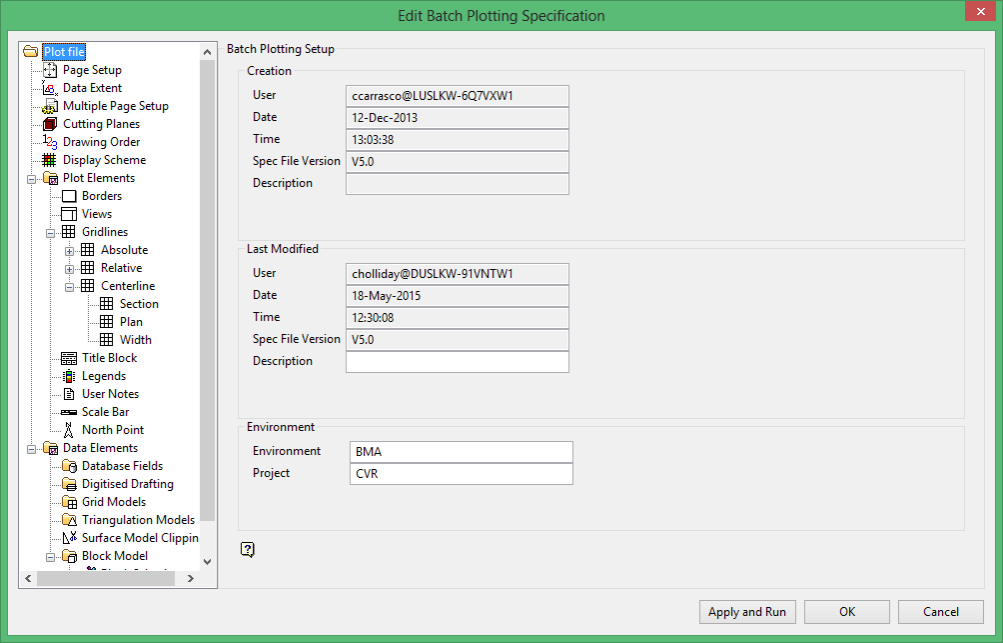
This interface consists of two sections, the tree control on the left and individual panels on the right. The panels displayed on the right depend upon the option selected from the tree control. To resize the interface, click and drag one of the corners.
Note: The drop-down list displays of all of the .dh2 files found in your current working directory. This may take a while to generate depending on how many files are found in your directory.
At any time you can click OK to save the specification file and to exit the option. The specification file is saved into your current working directory with the name <proj><name>.dh2 here <proj> is the project code, and <name> is the name that you specified on the front panel.
Click Apply and Run to save the specification file and to create the plot file. The progress of the plot file creation (and any errors) displays in a console window. Once the plot file has been created, a preview of the plot displays in the Plot Utility.
The panel displayed when you first select Batch Plotting (see diagram above) contains information about the creation and modification of the specification file, as well as displaying the environment and project codes.
Batch Plotting is separated into three sections, setting up page and data extents, plot elements (that is borders, scale bar etc.) and Data Elements (that is digitised data, triangulations etc.), documentation is provided for each section, plus a series of examples demonstrating the use of Batch Plotting are also provided.
Related topics

