Contour
Use Contour to calculate and display contours on the screen. These contours can be generated to include or exclude specific levels and may be saved (as reserving limits and/or masks) to the currently active design database for later use. These contours do not have annotations. This option is used to generate limit lines for grid visualisation and reserving.
The resulting contours displays as an underlay if the Automatically display contours preference has been set, or if you are not saving the contours to a design database. Refer to the Preferences option for more information.
Instructions
On the Grid Calc menu, point to Contour and Limit Generation, and then click Contour to display the Contour panel.
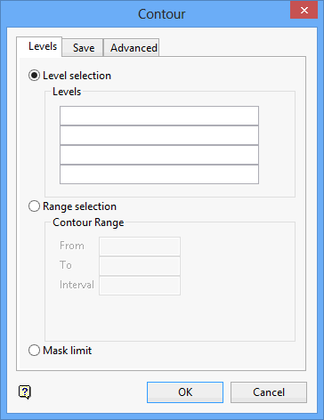
Levels tab
Level Selection
Select this option to contour specific levels. For example, for a thickness grid use 0.01 and select Greater than (under the Advanced tab ) to generate a contour that includes only the grid cells with values greater than 0.01 metres. The levels to contour must be greater than 0.
Range Selection
Select this option to contour a specific range. Enter the lower (From) and upper (To) range, as well as the contouring interval. The overall range of contours can be user-defined or will be determined by the grid values. For example, an interval of 10 will generate contours at level 10, 20, 30 etc. in the range of the data or a specified range.
The options under the Rules section of the Advanced tab can be used to apply further restrictions.
Mask Limit
Select this option to contour the mask of a grid.
Save tab
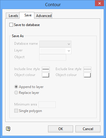
Check the Save to database check box to save the contour lines and polygons to a design database. The number of contour lines and polygons constructed displays in the Grid Calc Window prior to saving data to the nominated design database.You will be required to specify the name of the design database, as well as the name of the layer that will be used to store the contours. If you have chosen to contour a specific range (through using the Range Selection option), then the following naming convention will be applied to the specified layer name:
<layer><level>
where
<layer> refers to the name of the layer used to store the contours and
<level> refers to the level being contoured.
If you specify a layer name of Cnt, and levels 10, 15 and 20 were being contoured, then the resulting layers would be named Cnt10, Cnt15 and Cnt20.
Object
Specify an object name for the contours. The name will be incremented by one for each contour. If Cnt_0.8 is the supplied name, then the objects will be named Cnt_0.81, Cnt_0.82, Cnt_0.83.
Include Line Style
Select a line style for the include line type. Which is clockwise and all masked grid areas in the polygon are visible. If the limit is used in reserving, then the grid masked areas will be included in the reserves. The line style is selected from a list of line types delivered with Vulcan.
Object colour
Select a colour for the include line type. The colour is selected from the current colour table.
Exclude Line Style
Select a line style for the exclude line type. Which is anticlockwise and must be contained in an 'include' polygon. These 'excluded' areas will be invisible when the grid is masked with the layer, and will be excluded from all reserves if the limit is used in reserving. The line style is selected from a list of line types delivered with Vulcan.
Object colour
Select a colour for the exclude line type. The colour is selected from the current colour table.
You will have the choice of either appending the contours to an existing design layer or replacing (overwriting) the contents of an existing layer. If an object with the same name already exists in the layer, then it will be overwritten.
Minimum area
Enter the minimum allowable polygon area. Thus eliminating the possible creation of numerous tiny polygons.
Single polygon
Select this check box to save all polygons as a single object. Single polygons have an invisible bridge connecting the objects. Single polygons are used by the Report Reserves option (under the Rsvute > Reserves submenu).
Advanced tab
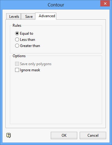
Rules
The following options are only applicable when using the Level Selection and Range Selection options (under the Levels tab ).
Equal to
Select this option to create contours at Z-values equal to the specified values.
Less than
Select this option to create contours that enclose regions of the grid that have Z-values less than the specified values.
Greater than
Select this option to create contours that enclose regions of the grid that have Z-values greater than the specified values.
Options
Save only polygons
Select this check box if you only want to save the constructed polygons. If this check box is not ticked, then both the contour lines and polygons will be saved to the nominated design database.
Ignore mask
Select this check box to ignore the mask value of a cell when contouring.
Click OK.
The resulting contours displays as an underlay if the Automatically display contours preference has been set, or if you are not saving the contours to a design database.
Contour lines with coincident start and end points are created as closed polygons.

