Create HARP Model
A HARP (Horizon Adaptive Rectangular Prism) model represents an entire Integrated Stratigraphic Model in a single Block Model file. The HARP model is created directly from grids or faulted triangulations. All quality grids are automatically incorporated. Use the Create Stratigraphic Block Model option to create a stratigraphic block model from a set of triangulations or a collection of stratigraphic grid models created through the Grid Calc menu.
You can also create a stratigraphic block model through using the bstrat and bstrat2 executables.
Block models constructed through this option do not result in the creation of an associated Block definition file (.bdf). As a result these block models cannot be used with options that require a .bdf file.
Contents:
HARP vs Bstrat Models
Traditional stratigraphic block models, also known as Bstrat models, were used prior to Vulcan version 8.0 to represent stratigraphic deposits. Like all traditional block models, each block was formed by a cuboid. As each vertex of the cuboid is formed with right angles, the blocks could not adequately represent roof and floor structures.
A HARP model block contains 5 points in the roof of the block and 5 points in the block floor. These points allow vertex angles to fluctuate, which allows the block to conform to structure roof and floor grids.
It is still possible to create traditional Bstrat model, similar to those created in Vulcan 7.5 and prior, which, like HARP blocks, are infinitely variable in the z-direction as to better represent the thickness of a horizon at a given block footprint. However, Bstrat models have a standard block structure whereby each block is a simple rectangular prism defined by a centroid point and X, Y and Z extents.
HARP models accurately resolve horizons down to a few centimetres or inches of thickness without the need to make huge models with extremely small Z sub-blocking.
In virtually all cases, a HARP model is recommended over a traditional block model.
On the Grid Calc menu, point to Integrated Stratigraphic Modelling, and then click Create HARP Model to display the Create Stratigraphic Block Model panel.
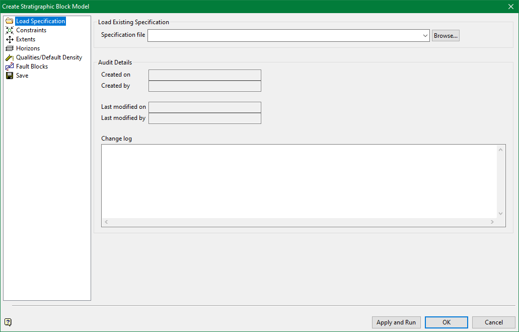
Load Specification
Select an existing bstrat2_spec Specification file from the drop down list. Click Browse if the file is located in a folder other than the current work area.
Audit details are automatically populated when the specification is created. The details will update each time the specification is run. Enter pertinent details of a particular specification run in the Change Log area. Entries are saved in the specification file for auditing purposes.
Constraints
The Constraints pane controls the sensitivity of the Plan view sub-blocking which is defined on the Extents pane. This is controlled by:
-
Setting a minimum allowable horizon height.
-
Limiting the vertical extent of the model.
-
The decision to create a HARP, Bstrat or Regular model.
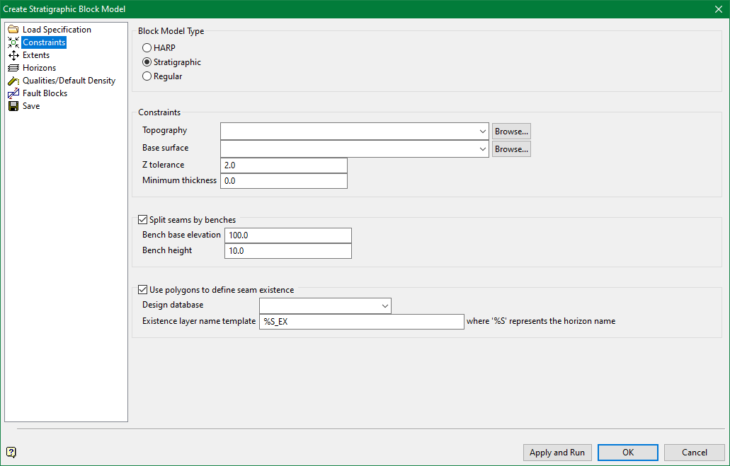
Block Model Types
-
Select HARP to generate a HARP model with smoothed top and bottom block surfaces.
-
Choose Stratigraphic to generate a Bstrat model, which is similar to the HARP model, but does not have additional top and bottom points or flexible corners. Bstrat models are useful when bench levels are inherent to the block model.
-
Select Regular to create a regular block model, typically used for subsequent Pit Optimisation work.
Although HARP models take longer to generate than Bstrat models, HARP models are far more accurate. To obtain a Bstrat model with anywhere near the same volumetric fidelity of a HARP model requires that the blocks generate at a much smaller block size. Therefore, a HARP model may take less time to create than a Bstrat model of the same quality.
If generating a HARP model, Split by benches is disabled. Break down output reports by bench with options in Block > Advanced Reserves.
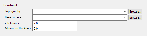
Topography
Topography is defined with any grid or triangulation surface which represents the uppermost structural limit of the model.
Create this surface a little higher than required. This method is useful when reserving a subsequent month end topography, which has some material pushed up above the current one.
Base Surface
Select a grid or triangulation surface which represents the lowermost limit of modelling.
Create the surface a little lower than required. This method is useful when reserving a pit where the floor is in some places slightly below the lowermost economic horizon.
Z Tolerance
The value works in conjunction with the Number of sub-blocks in both X and Y directions set on the Extents pane.
Units are defined by the .dg1 file configuration.
The model is created at the finest resolution block size. Using the values in Diagram 1, blocks are created at 50 x 50. After the model is created at the finest resolution, the elevation of consecutive block centroids is compared.
-
If the difference in elevation between two blocks exceeds the defined Z tolerance then sub-blocks are kept.
-
If the difference is less than the Z tolerance, the parent block size is retained.
Therefore, a smaller Z tolerance results in more sub-blocking.
Although possible, no sub-blocking is required in the Z direction as a Bstrat or HARP model has an infinitely variable block height.
There are five points defining the top and base of each block in a HARP model so that HARP blocks may respect undulating surfaces. This greatly reduces the need to sub-block in X and Y directions.
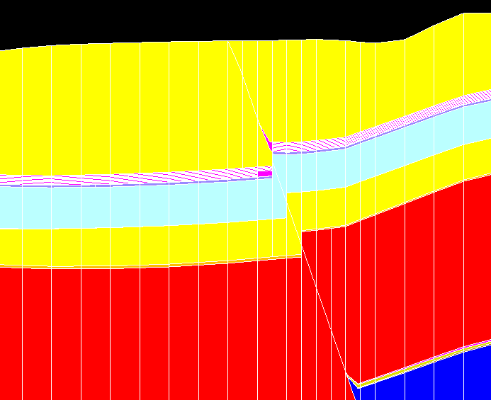
Figure 1: Cross-sectional slice through a HARP model
Above is a cross-section through a HARP model. Note that the blocks exactly honour provided surfaces. The distance between vertical lines represent X and Y block boundaries. Note how spacing tightens when resolving the fault plane.
Minimum thickness
Any block with a height less than the entered value will not generate. Instead, the block will merge with the block beneath it. Enter 0.0 to create all blocks.
Split Seams by Bench
This option is available when generating a Stratigraphic model.
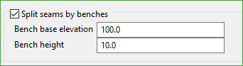
Check Split seams by benches (non-HARP only) to insert horizontal benches into the structure of the Bstrat model. This will add extra blocks.
The benches are created at the entered Bench height. The Bench base elevation provides a reference level for bench creation.
All possible blocks falling within the vertical extent of the Bstrat model are created, irrespective of the level of the base elevation.
Use Polygons to define seam existence
Select this option to impose seam existence relationships into a HARP model.
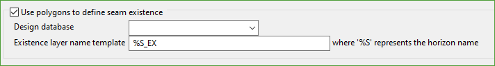
HARP models do not require masking or pinching to represent seam splitting or exclusions as each HARP block has a single value for the seam variable.
Select an available Design Database from the drop-down list.
Existence layer name template
The required format for layer naming template is %S_EX, where %S represents the horizon name and _EX can be customised to your need. The required naming format is the panel default in Grid Calc > Integrated Stratigraphic Modelling > Model Stratigraphy.
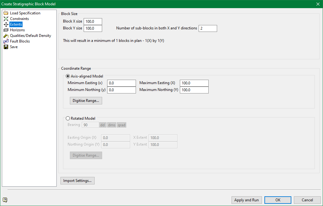
Extents
Define Cartesian or Rotated Plan extents and initial X and Y block sizes. Entered parameters are used to generate panel feedback as to the size of the resultant model. The estimated block model size is displayed under Block Size.
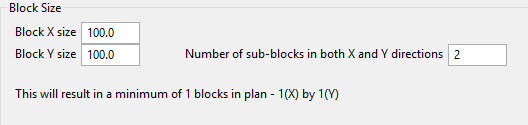
Block Size
Enter the required block size in both X and Y directions. These sizes do not have to be the same, nor do they have to represent the same dimensions as any grids or triangulations used to create the model.
Unlike conventional block models, the value entered for Number of sub-blocks in both X and Y directions is a divisor; not an absolute block size.
Coordinate Range
-
Select Axis-aligned Model to specify model extents in Cartesian space.
-
Select Rotated Model to specify extents in any rotation about the z-axis.
Whether the model is Axis-aligned or Rotated, specify extents with one of the following methods:
-
Manually enter Easting and Northing values.
If the model is rotated, additional entries are required. Enter a Bearing ranging from 0-360 degrees. Also enter X Extent and Y Extent values.
-
Click Digitise range to interactively digitise extents in Vulcan.
When digitising rotated extents, try to draw the rectangle so that the angle of rotation is always defined as a positive angle.
-
Click Import Settings to populate the panel with values from a previous HARP specification (
.bstrat2_spec) or Stratigraphic Modelling specification (.sme_spec).
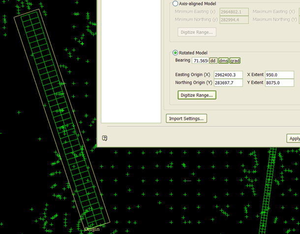
Figure 2: The rectangle around pit strip is a digitised HARP model.
Extents are automatically rounded to multiples of the specified block size. This could present problems if the block size is almost as large as the extents. For example, if the block size is 100 units but the required extents measure 325 units.
Defined extents do not need to encompass the entire Stratigraphic modelling area. Therefore, it is possible to create a HARP model at a local area of interest. A good example is a model of a single pit.
After defining an extent, Vulcan calculates how many parent blocks are expected in the HARP model of a single horizon.
Sub-blocks are ignored when estimating block counts. To obtain a reasonable estimate of the total number of blocks required to model a deposit using sub-blocks, multiply the estimated number of blocks by twice the number of horizons in the model.
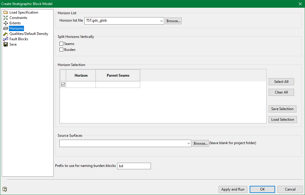
Horizons
This pane accesses the horizons as stored in a. gdc_glob global horizon list file.
The horizon list is used to select relevant structural triangulation and grids. It is important that the horizon list coordinates with available triangulation and grid surfaces, and that the surfaces follow the expected naming convention.
-
If models were created without faulting, the grids are used to create the HARP model. Grids are named with the convention
<proj><horizon>.srg or <proj><horizon>.sfg, where <proj> is the project prefix and <horizon> matches what is defined in the.gdc_blobfile. -
If models were created with fault throws which include dips, unclipped triangulations are used to create the HARP model. Triangulations are named with the convention <proj><horizon>.srg or
<proj><horizon>.sfg, where <proj> is the project prefix and <horizon> matches what is defined in the.gdc_blobfile. -
If models were created with fault blocks, unclipped triangulations are used to create the HARP model. Triangulations are named with the convention
<proj><horizon><fault block name>.srgor<proj><horizon><fault block name>.sfg, where <proj> is the project prefix, <horizon> matches what is defined in the.gdc_blobfile, and <fault block name> matches the name of the input fault block triangulations.
Split Horizons Vertically
By default, block heights will correspond to horizon thicknesses. Select between two options for Split Horizons Vertically to divide horizons in the z-direction:
-
Seam Split Height
-
Burden Split Height
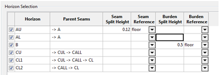
In above diagram, AU is divided into 0.12 unit vertical blocks. The Reference point for this division is the floor of the AU horizon. Similarly, the burden interval between the B and AL seams are split into 0.5 unit vertical blocks. However, these splits are based on the floor of the B horizon.
If a HARP model is created, the blocks echo the roof or floor shape.
When splitting blocks in the z-direction using the roof or floor or a horizon as a reference, additional variables are added to the HARP model. This allows for refined block selection within horizons when using the HARP model.
-
If the roof is used as the reference level, the subnroof variable is created.
-
If the floor is used as the reference level, the subnfloor variable is created.
The value of the variable corresponds to a number which defines a given block’s sequence within a specific horizon.
Due to potential conflicts between the surfaces used to create a HARP block, all options which try to include RL-based levels into the Block Model are disabled if a HARP model is selected on the Constraints pane.
RL-based levels are available for a Stratigraphic block model.
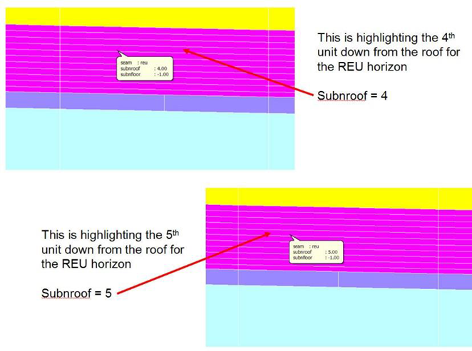
Figure 3: How the subnroof block model variable populates
Source surfaces

Structural horizon models are used to create the HARP model framework. Input surfaces are grid models or triangulations, which are typically created in Grid Calc > Integrated Stratigraphic Modelling > Model Stratigraphy.
-
If models were created without faulting, the grids are used to create the HARP model. Grids are named with the convention <proj><horizon>.srg or <proj><horizon>.sfg, where <proj> is the project prefix and <horizon> matches what is defined in the
.gdc_blobfile. -
If models were created with fault throws which include dips, unclipped triangulations are used to create the HARP model. Triangulations are named with the convention <proj><horizon>.srg or <proj><horizon>.sfg, where <proj> is the project prefix and <horizon> matches what is defined in the
.gdc_blobfile. -
If models were created with fault blocks, unclipped triangulations are used to create the HARP model. Triangulations are named with the convention <proj><horizon><fault block name>.srg or <proj><horizon><fault block name>.sfg, where <proj> is the project prefix, <horizon> matches what is defined in the
.gdc_blobfile, and <fault block name> matches the name of the input fault block triangulations.
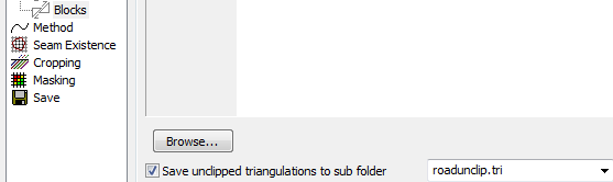
When modelling faults with triangulation solids, it is possible to save clipped, faulted triangulations. Do not use these triangulations when creating a HARP model.
Instead, use the unclipped triangulations. Unclipped triangulations are analogous to unmasked grids. These are more appropriate for creating HARP models.
The destination for these unclipped triangulations must match the source defined in Grid Calc > Integrated Stratigraphic Modelling > Model Stratigraphy.
-
If throw faults were defined in Grid Calc > Integrated Stratigraphic Modelling > Model Stratigraphy > Faulting > Throw, a single, complexly faulted surface was created for each roof and floor. Corresponding to these surfaces are special mask grids representing the area of influence of each fault string. Each masking grid has an MKG extension and a master_mask identifier.
If one of these master mask files is found within the selected Source surfaces directory, the HARP creation option will automatically change to a creation format suited to this input type. A message is displayed on the panel.
If the deposit is not faulted with triangulation solids during creation with Grid Calc > Integrated Stratigraphic Modelling > Model Stratigraphy, the input surfaces are grids. The naming convention for the grids is:
-
<projectcode><horizon>.srg for structure roofs
-
<projectcode><horizon>.sfg for structure floors
Prefix for Mining Burden Blocks

A HARP model variable named seam is automatically created. This variable stores the horizon name defined in the horizon list.
Any burden, defined as waste above a horizon, is identified by the horizon name concatenated with the Prefix to use for naming burden blocks.
U sing the configuration illustrated in Diagram 9, any waste blocks above a horizon named ORL are identified with a bdorl value in the seam variable. This is because the Prefix to use for naming burden grids is bd.
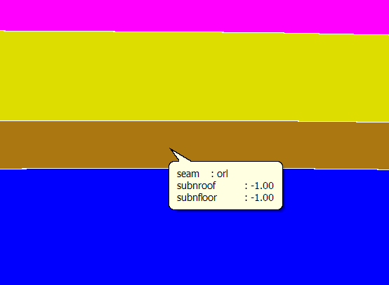
Figure 4: Brown blocks represent the orl horizon
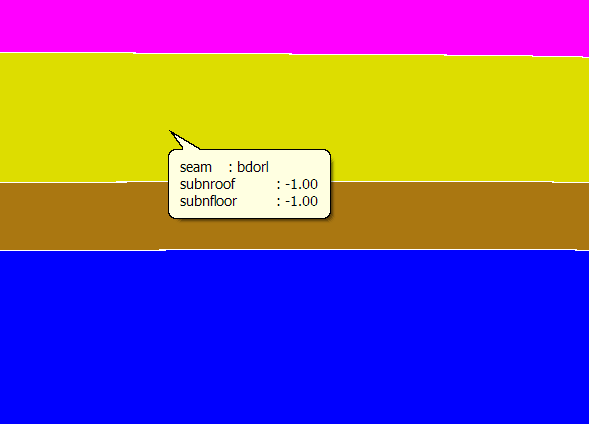
Figure 5: Yellow blocks represent burden of the orl horizon
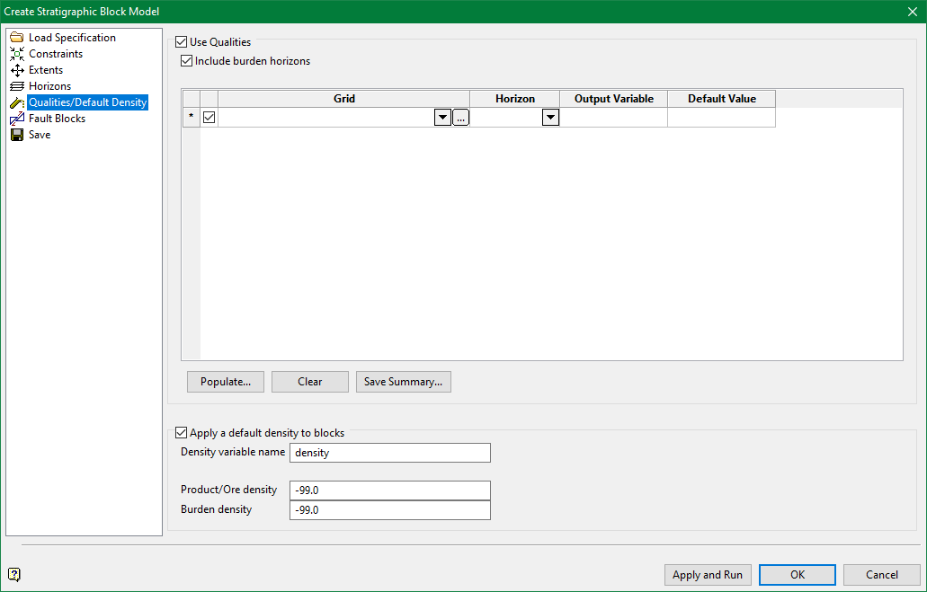
Qualities /Default Density
Check Use Qualities to designate quality grids used to populate the resulting HARP model. If grids are named with the standard naming convention, the appropriate quality grid value is automatically associated with the relevant block in the HARP model based on the horizon variable. The grid value is populated into the HARP block vertically above the grid cell.
Select Include burden horizons to assign quality information to burden horizons. Match appropriate grids to the burdens in the panel.
Click Populate to automatically correlate input grids to output HARP model variables. If required, it is possible to define these connections manually.
If qualities are not in grid form, select Block > Grade Estimation to populate the resulting HARP model.
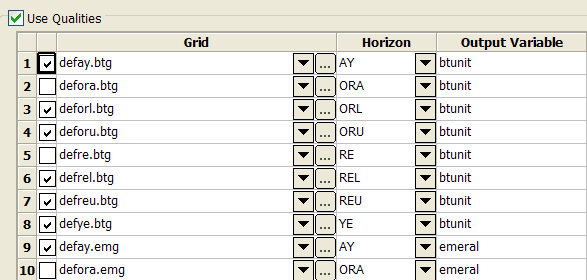
The main panel has four main columns;
- Input quality Grid(s), including a data path if the grid is not in the current work area.
- The Horizon associated with the quality grid.
- The Output Variable which will hold the quality values in the resultant HARP model.
- A Default Value populated to unassigned blocks.
If no Default is entered, the system assumes a default value of -99.
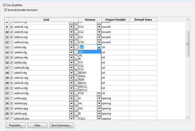
Grid Definition
There are two methods for defining input Grids.
- Manually configure Grid selection from drop-down lists.
- Click
 to automatically configure the Qualities.
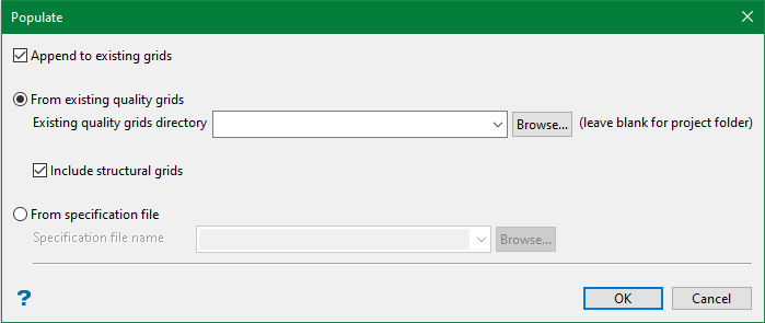
Select Append to existing grids to build the final input list from several runs. Deselect this option to overwrite.
Select From existing quality grids to use quality grids based upon folder location. Leave the field blank if the grids are in the root of the current work area. Click Browse if the grids are located in a subfolder within the current work area or elsewhere on the local computer or network.
Include structural grids will include grids with stor tkextensions as input.
Select From specification file to populate this panel from a specification file. Specification files are generated by the following options:
- Grid Calc > Integrated Stratigraphic Modelling > Create HARP Model
- Grid Calc > Integrated Stratigraphic Modelling
- Grid Calc > Create Multiple Surfaces.
Click OK to populate the main panel with quality grids. This may take a few seconds if there are many grids or if the grids are accessed over a busy network.
The output variable is automatically populated from variable values in grid headers. The following procedure explains how this works:
-
btunit and emeral originate from the Grid Calc > Integrated Stratigraphic Modelling > Composite and Model Qualities panel. (See Diagram 3.) BTUNIT and EMERAL were entered as compositing variable names, which define column headers in resultant quality Mapfiles or Mapbases.
-
When creating quality grids from the Mapfiles or Mapbases through Grid Calc > Integrated Stratigraphic Modelling > Composite and Model Qualities or Grid Calc > Create Multiple Surfaces, these identifiers are automatically suggested as the variable identifiers for the grids. The variable value is encoded directly into the binary header of the grids themselves.
-
Grid Calc > Integrated Stratigraphic Modelling > Create HARP model populates the HARP model variable names from the variable encoded into grid headers.
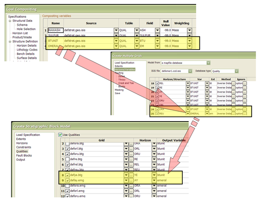
Figure 6: Origin of automatically-populated Output Variables
Grids created prior to Vulcan 8 or those not created using Integrated Stratigraphic Modelling will not have grid headers. However, if these grids are named with an underscore ( _ ) after the horizon name and before the grid extension, the characters between the underscore and grid extension are used to automatically populate the Output Variable for the HARP model.
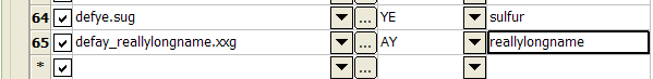
7- Output Variable population using an underscore in the grid name
7 contains a grid named defay_reallylongname.xxg where;
- def is the project code
- ay is the horizon name, and
- reallylongname is the required HARP model output variable name.
Click Save Summary to save the contents of this panel as a formatted text file for auditing purposes.
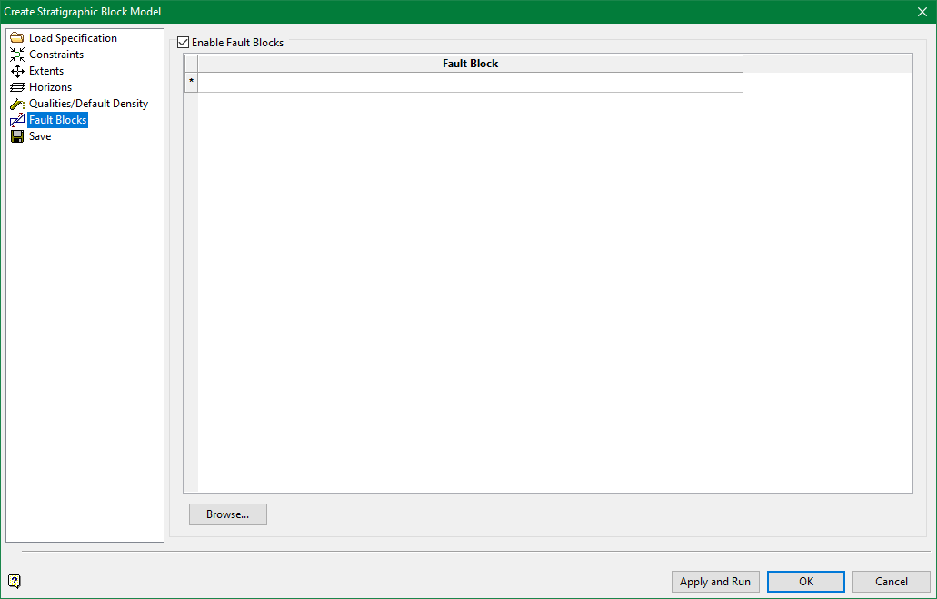
Fault Blocks
Check Enable Fault Blocks if the original structural grids were created with fault blocks in Grid Calc > Integrated Stratigraphic Modelling > Model Stratigraphy.

I f fault blocks were not used when generating structural grids, do not check Enable Fault Blocks. If fault blocks are not enabled, grid files are used as surface input information when creating the HARP model. These input files are specified in the Horizons pane.
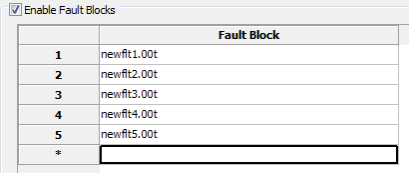
To use fault blocks, direct the HARP model creation panel to the location of two data sources.
-
The location of the unclipped faulted triangulation files. These were created in Grid Calc > Integrated Stratigraphic Modelling > Model Stratigraphy and specified in the Horizons pane Grid Calc > Integrated Stratigraphic Modelling > Create HARP Model.
-
The location of the Fault Block solid triangulations used when creating faulted structural grids in Grid Calc > Integrated Stratigraphic Modelling > Model Stratigraphy.
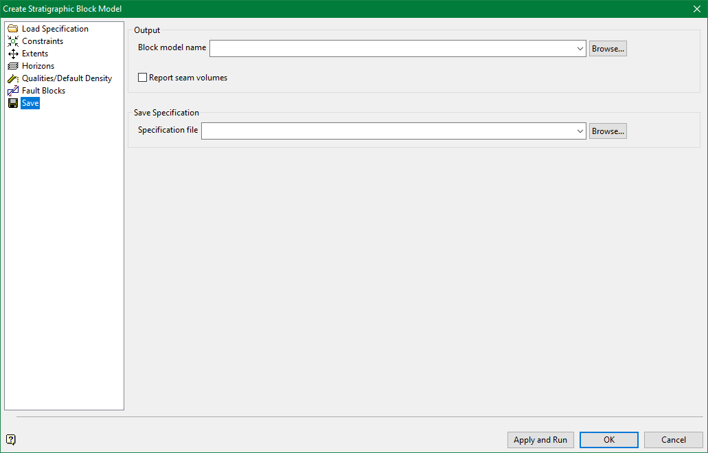
Save
Output
Enter block model and specification file names. Both Bstrat and HARP models will have a .bmf extension. The specification file will have a. bstrat2_spec extension. Click Browse to generate these files to a location other than the current work area.
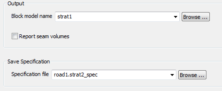
Check Report seam volumes to calculate a very basic comparison of volumes. The volumes are reported to the TSCH window output. This compares the HARP model volume with the underlying Bstrat model volumes. This is not intended to replace proper reserve reporting created by Block > Advanced Reserves.
Click Apply and Run to save the specification and create the model. HARP model creation process commences in a TCSH window.
It is possible to create a HARP model directly from the TCSH via the bstrat2 command with the syntax:
bstrat2 (<full specification name>.bstrat2_spec )

