Set Up
Use the Set Up option to open a design file and, at the same time, change its default design parameters.The Load option can also be used to open a design file, however, you are unable to change the design parameters. The design parameters relate to:
- alignment
- intersection points
- super elevation values
- slope of batters
The parameters are stored in the file named <proj><design_name>.ron. See Appendix A for an example. The Topography, Subsurface, Bulking Factor and Haul Costs options allow you to change additional system defaults. The text settings specified under the Defaults : 2D Text section of the Tools > Preferences option are used when labelling the plot of the road design.
Note The additional defaults can also be set when creating the actual design.Instructions
On the Iroad menu, point to Files, and then click Set Up to display the Enter the following panel.
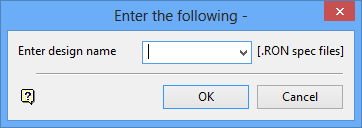
Enter design name
Enter the name of the design file to load. The open file becomes the default design file for the remainder of the Vulcan session.
Click OK.
The Road Design Set Up panel displays
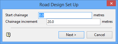
Use this panel to change the default alignment parameters.
Start chainage
Enter the start of the chainage. The unit of measurement is set in the .dg1 file.
Chainage increment
Enter the interval between the chainage points. The unit of measurement is set in the .dgq2 file.
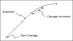
Figure 1: Chainage
Click Next.
The Alignment Defaults panel displays.
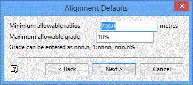
Use this panel to change the defaults for the generation of intersection points.
Minimum allowable radius
Enter the minimum radius. This is the smallest radius for the design. The unit of measurement is set in the .dg1 file.
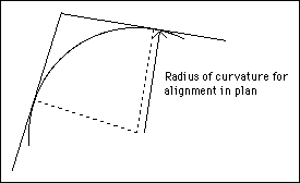
Figure 2: Minimum Allowable Radius
Maximum allowable grade
Enter the maximum grade. This is the steepest grade, either going up or down, for the design. The grade can be entered as decimal degrees (nnn.n), as a normal grade specification (1:nnnn) or as a percentage grade (nnn.n%). See also Appendix B : Notes on Slopes and Grades.

Figure 3: Maximum Allowable Grade
Click Next.
The Road Design Cross Section Superelevation panel displays.
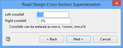
Use this panel to change the default super elevation values to use when no designed super elevation diagram is used for the generation of cross sections
Left crossfall/Right crossfall
Enter the left and right cross fall. These can be entered as decimal degrees (nnn.n), as a normal grade specification (1:nnnn) or as a percentage grade (nnn.n%). See also Appendix B. A negative crossfall indicates a downward slope from the centre of the road (see Diagram 4). The cross fall values apply only to the road centre lanes. The shoulders and verges take on the appropriate values depending on the centre lanes crossfall.

Figure 4: Crossfalls
Click Next.
The Road Design Cross Section Batters panel displays.
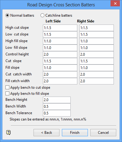
Use this panel to change the slope values of batters that are used when cross sections are generated.
Batters can be specified as either Normal or Catchline type. The main difference is that the slope for normal batters is always fixed, whereas the slope for catchline batters can vary under certain circumstances to make a constant plan distance between the edge of the road and where the batter intersects the surface constant.
With normal batters, two different slopes can be applied in each of cut or fill (see Diagrams 5a and 5b). In the case of the road cutting the topography, if the height from the edge of the road to a point on the topography vertically above (h) is less than the control height (H), then the low cut slope batter is used. If h is greater than H, then the high cut slope batter is used. The same can be said for the fill condition.

5a - Normal Batters

5b - Normal Batters
Catchline batters look the same as normal batters when the height (h) is greater than the control height (H). However, when the height is lower, the catchline distance is used to define the slope (see Diagrams 5c and 5d). Catchline batters can be used to give a more aesthetically pleasing design if the absolute value of the batters are not crucial, since the edge of the road and where the batter intersects the topography, form parallel lines.
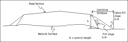
5c - Catchline Batters
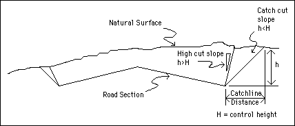
5d - Catchline Batters
Slope values can be entered as decimal degrees (nnn.n), as a normal grade specification (1:nnnn) or as a percentage grade (nnn.n%). See also Appendix B : Notes on Slopes and Grades.
Apply bench to cut slope
Select this check box to incorporate benched into the cut slope.
Apply bench to fill slope
Select this check box to incorporate benches into the fill slope.
Enter the height and width for the benches, as well as a tolerance value. Benches that fall below the specified tolerance value will be added to the preceding bench instead of being created. A tolerance value is specifically used to prevent the creation of small and unwanted benches.
Click Finish.
The defaults are stored in the <proj><design_name>.ron file. See Appendix A for an example. You may then want to set the default topography, subsurfaces, haul costs, label size and bulking factor.

