Intersection Points
Use the Intersection Points option to create or modify intersection points (IPs). For horizontal intersection points, you must be in plan view (Primary Window). For vertical intersection points, you must be in long section view (LONG_SECT window). Look at the Status toolbar to see the current window.
Tip: Use Ctrl + Tab to cycle between windows.
Instructions
On the Iroad menu, point to Edit, and then click Intersection Points.
The panels and prompts that appear depend on the current window:
Primary (for horizontal points)
Long Section View (for vertical points)
Primary
The Design dialog box displays.
New_IP
Select this option to start a new IP design.
Old_IP
Select this option to modify an existing IP design.
New_IP
Indicate the first intersection point (any of the Design Entry modes can be used).
The following panel displays.
Easting/Northing
These fields show the easting and northing co-ordinates of the selected intersection point. These values can be overwritten.
Radius
The default radius is specified through the Set Up option. As this is the minimum allowable radius, your entry must be greater than this value.
Input spiral length/Output spiral length
Enter the input and output spiral lengths. These lengths define the length of a curve that will be fitted between, the tangent and circular part of the alignment. The spirals allow a smooth transition from a straight to circular curve. The input spiral is the length before the circular curve in the direction of the alignment. The output spiral is the length after the curve. The unit of measurement is set in the .dg1 file.
The curves are displayed when the alignment is created from the intersection points. By labelling the point names ( Analyse > Label > Point Label ) on the alignment, you can see where the various curves start and finish.
Click OK.
Indicate the next intersection point. The Horizontal intersection points panel is redisplayed. Cancel when you have finished indicating intersection points.
Each set of intersection points one object with the name IP<n> where n is an increasing integer. The W tag of each point holds the radius value. For each object, the file (<proj>design_name>ip<n>.hip) is generated. This file, which is stored in your working directory, contains the horizontal IP data (X, Y, W, input and output spiral length). The objects are placed in a layer named <design_name>.H. See Diagram 1 for a graphical explanation.
Figure 1: Horizontal Intersection Points
Old_IP
Select the set of intersection points to modify (i.e. an object with a name IP<n>). Select the point to modify. The Horizontal intersection points panel is then displayed as when creating new points.
Long Section View
The Design dialog box displays.
New_IP
Select this option to start a new IP design.
Old_IP
Select this option to modify an existing IP design.
New_IP
Indicate the first intersection point (any of the Design Entry modes can be used). Vulcan checks that the indicated point is in the maximum allowable grade defined in the Set Up option.
The following panel displays.
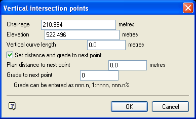
Chainage
This refers to the chainage of the indicated intersection point. It can be overwritten. The unit of measurement is set in the .dg1 file.
Elevation
This refers to the elevation of the indicated intersection point. It can be overwritten. The unit of measurement is set in the .dg1 file.
Vertical curve length
Enter the vertical curve length. This value is usually set to 0 (zero) for the first and last intersection points (see Diagram 2). The vertical curve length defaults to the last entered curve length after the first point. Vulcan checks to see if the curve length will actually fit given the previous curve and the distance back to the last point. The unit of measurement is set in the .dg1 file.
Figure 2: Vertical Curve Length
Set distance and grade to next point
Select this check box to set the next point at a fixed distance and grade from the current point (see Diagram 3). The grade can be entered as decimal degrees (nnn.n), as a normal grade specification (1:nnnn) or as a percentage (nnn.n%). See also Appendix B. You can also specify the next intersection point by clicking OK on the panel and indicating the point normally.

3- Set Distance and Grade to Next Point
Click OK.
If you didn't select the Set distance and grade to next point option, then indicate the point and the Vertical intersection points panel reappears. If the indicated point produces a gradient greater than the maximum allowable gradient set in the Set Up option, then an error message displays. An error message is also displayed if the parabola length is too large (see Vertical curve length).
Each set of intersection points are one object with the name IP<n> where n is an increasing integer. The W tag of each point holds the vertical curve length (parabola). The objects are placed in a layer named <design_name>.V. See Diagram 4 for a graphical explanation.
Figure 3: Vertical Intersection Points
Old_IP
Select the set of intersection points to modify (i.e. an object with a name IP<n>). Select the point to modify. The Vertical intersection points panel is then displayed as when creating new points.
If you edit a point with the Set distance method and grade to next point box ticked, then the next point will be placed a plan distance and gradient from the current point. Subsequent points in the alignment will be placed as shown in Diagram 5.
Figure 4: Set Distance Method

