Design Alignment
Use the Design Alignment option to generate both horizontal and vertical alignments. For horizontal alignments you must be in plan view (Primary Window). For vertical alignments you must be in long section view (LONG_SECT window). Look at the Status toolbar to see the current window.
Tip: Use Ctrl + Tab to cycle between windows.
Instructions
On the Iroad menu, point to Edit, and then click Design Alignment.
The panels and prompts that appear depend on the current window:
Primary (for horizontal points)
Long Section View (for vertical points)
Primary
Select the horizontal intersection points (i.e. an object with a name IP<n>). Confirm that the correct object was selected. The alignment is generated.
If the alignment cannot be created because the radius at a point is too large, then an error message displays referring to the problem point.
You are asked whether or not to keep this alignment.
The alignment consists of a string of easting and northing points. In addition, the W values of the points contain the chainage along the line, with increments equal to the default chainage increment.
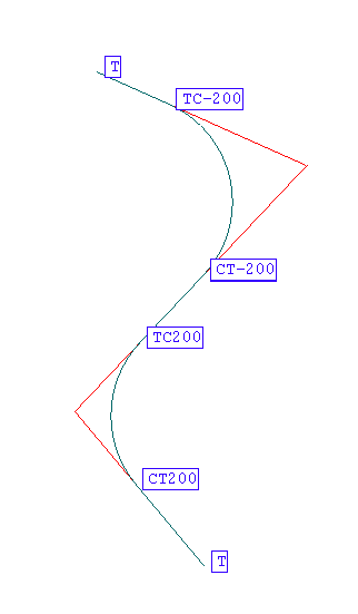
Points that are on a straight line are named T (Tangent). Points that are not on a straight line are named a combination of where two curves meet. For example, TS (Tangent to Spiral), SC (Spiral to Circular Curve), CS (Circular Curve to Spiral), ST (Spiral to Tangent). These points are also given a number. This number is the radius of the curve (for example TC200). A positive radius indicates the alignment is curving right, a negative radius indicates the alignment is curved left. Use the Analyse > Label > Point Label option to view the names. See Diagram 1 for an example.

Figure 1: Horizontal Alignment/Point Names
The alignment string is one object named ALNH. The object is placed into a layer named <design_name>.A.
Long Section View
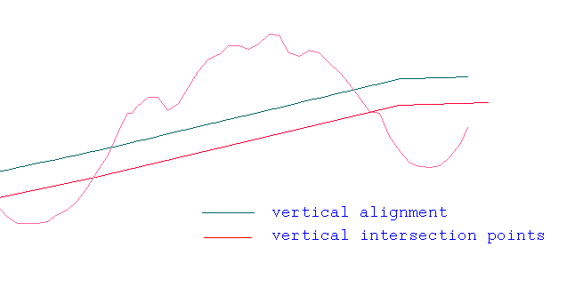
Select the vertical intersection points (i.e. an object with a name IP<n>). Confirm that the correct object was selected. Select the alignment (i.e. the horizontal alignment created earlier).The vertical alignment is generated. See Diagram 2.

2- Vertical Alignment
If the vertical alignment is being generated for the first time, then the alignment is a straight line (i.e. all the alignment points have the same elevation). The alignment string is one object with the name ALNV. The object is placed into a layer named <design_name>.A.

